Sampling Oscilloscopes to 30 GHz with TDR/TDT and Optical models
15 to 30 GHz electrical, 9.5 GHz optical, TDR/TDT, 2-channel and 4-channel, compact, portable, USB instruments.
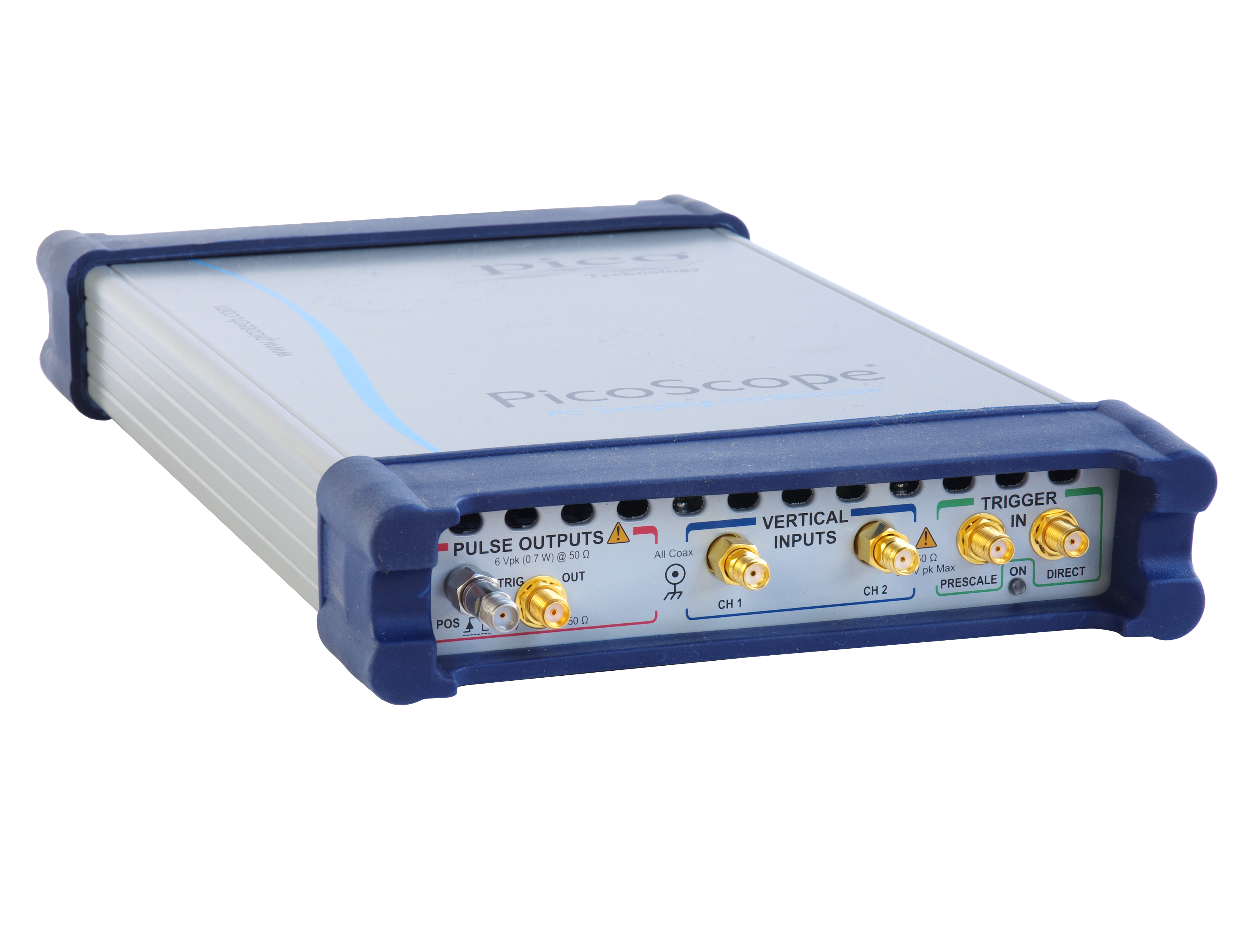
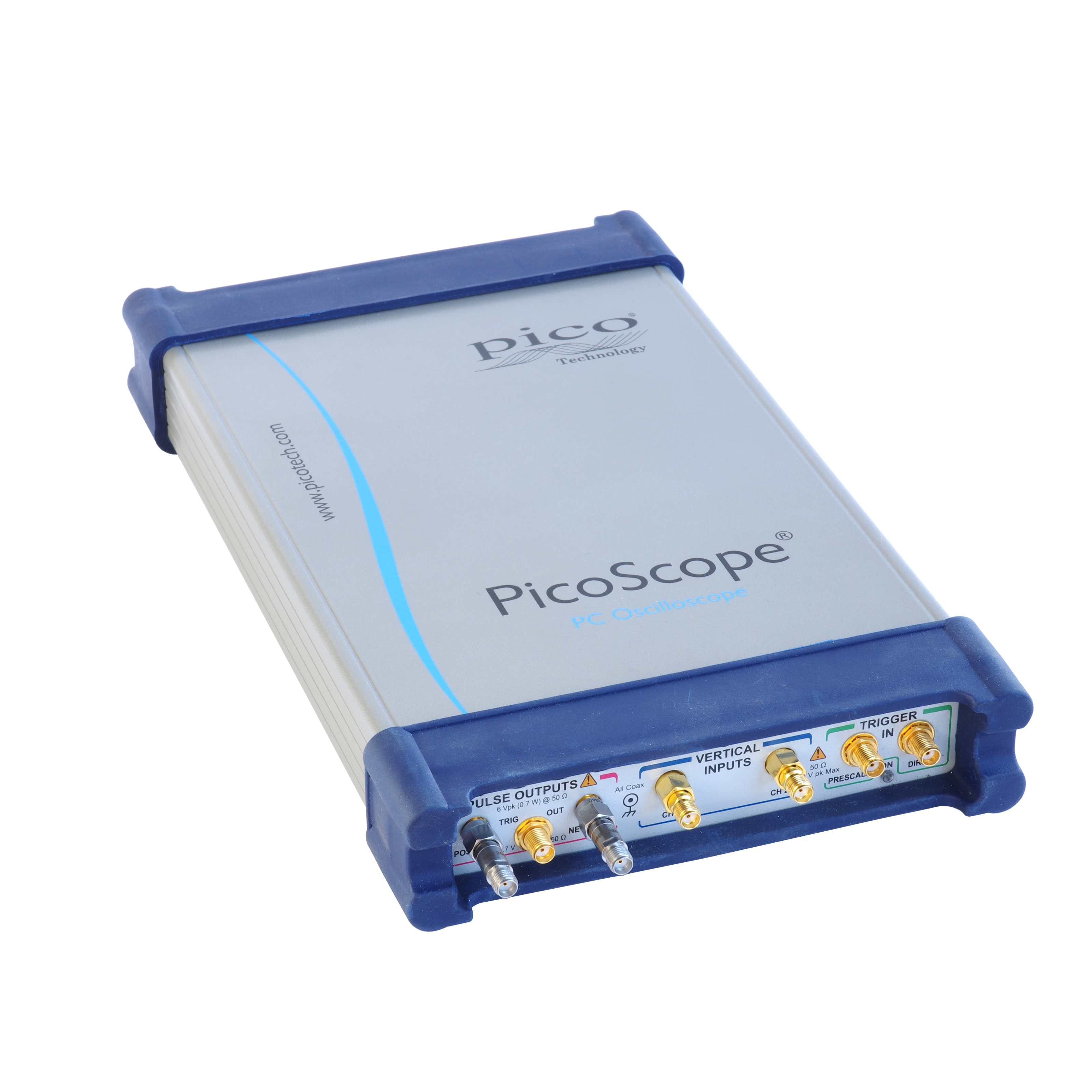
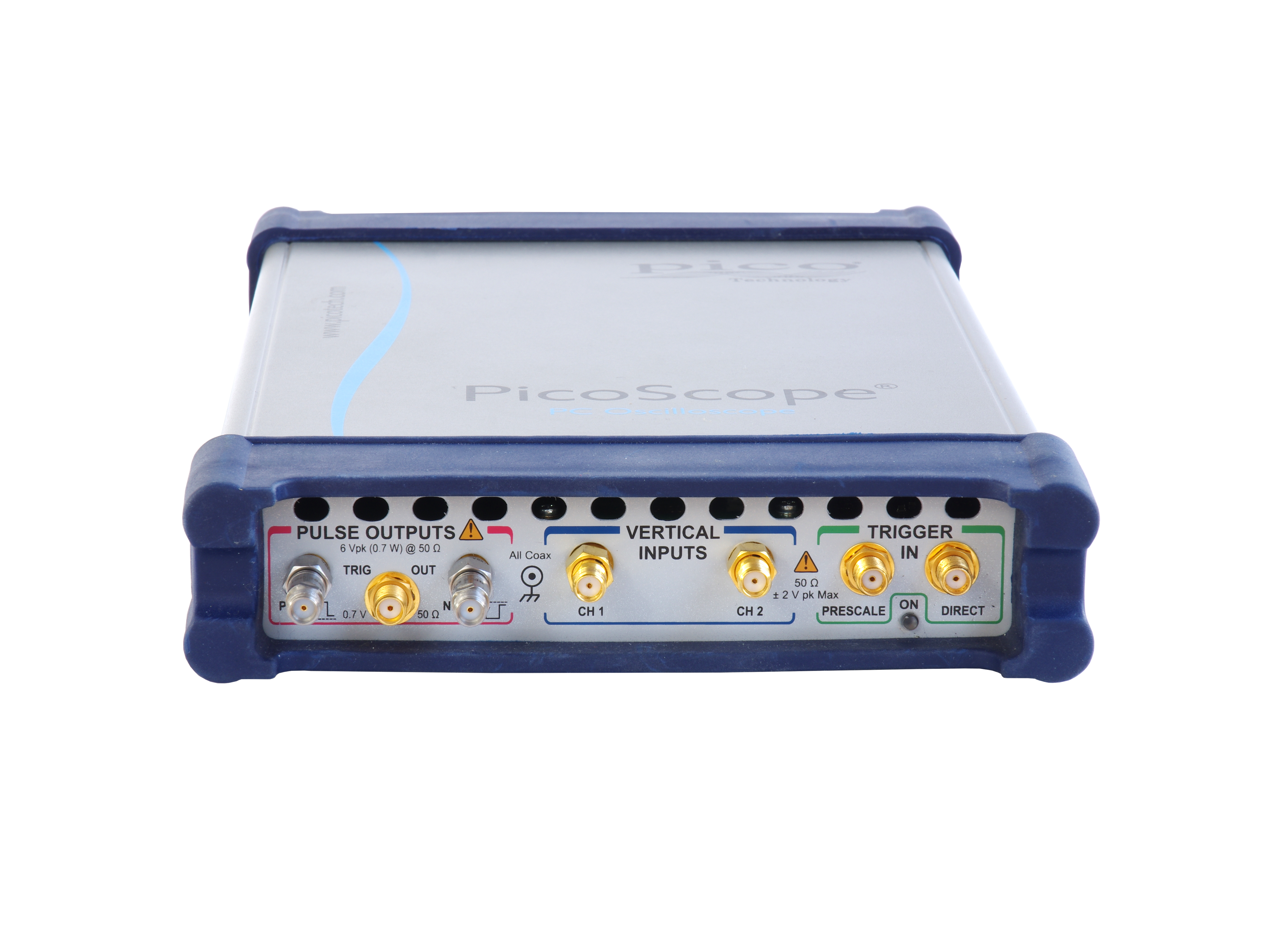
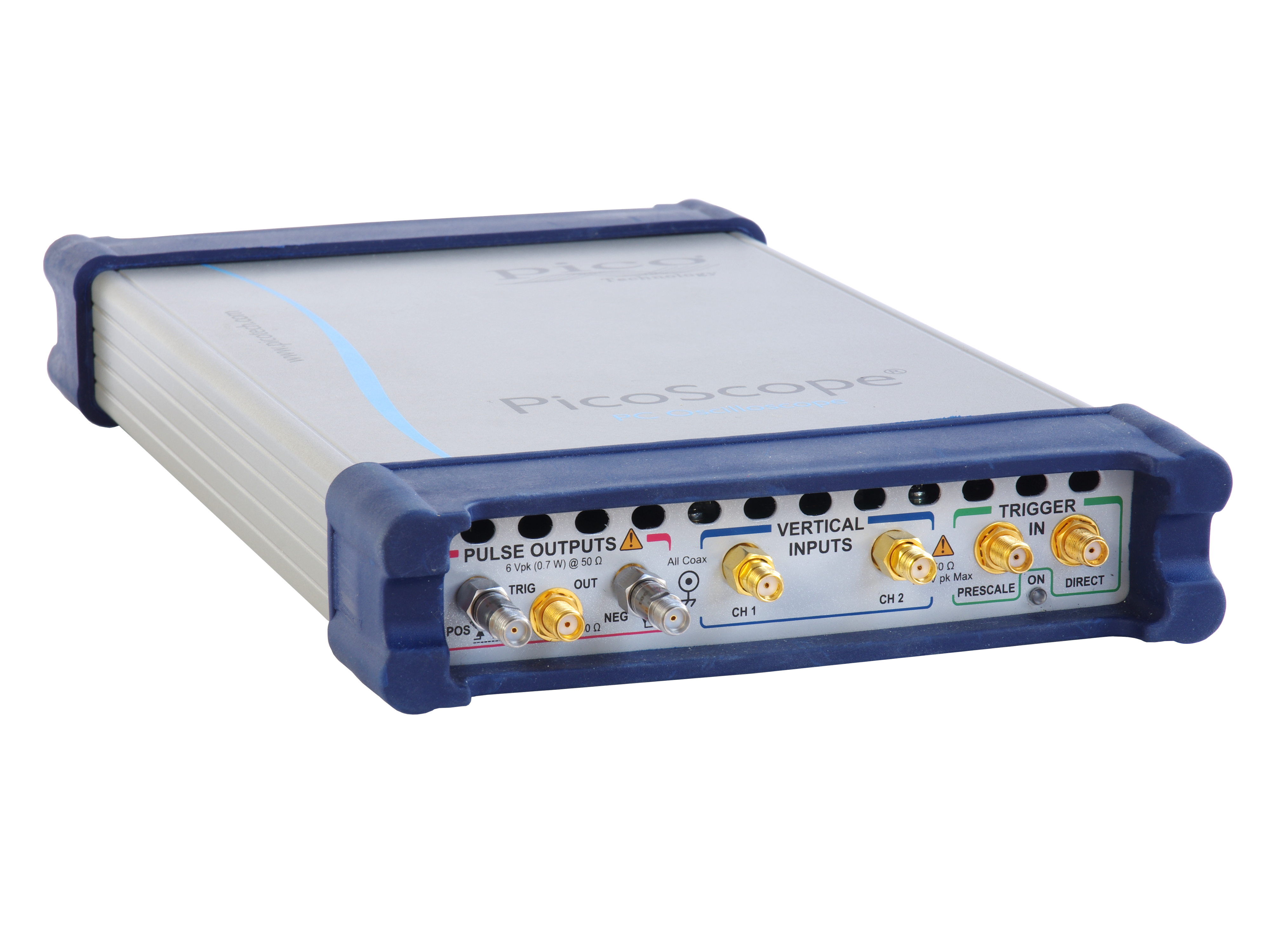
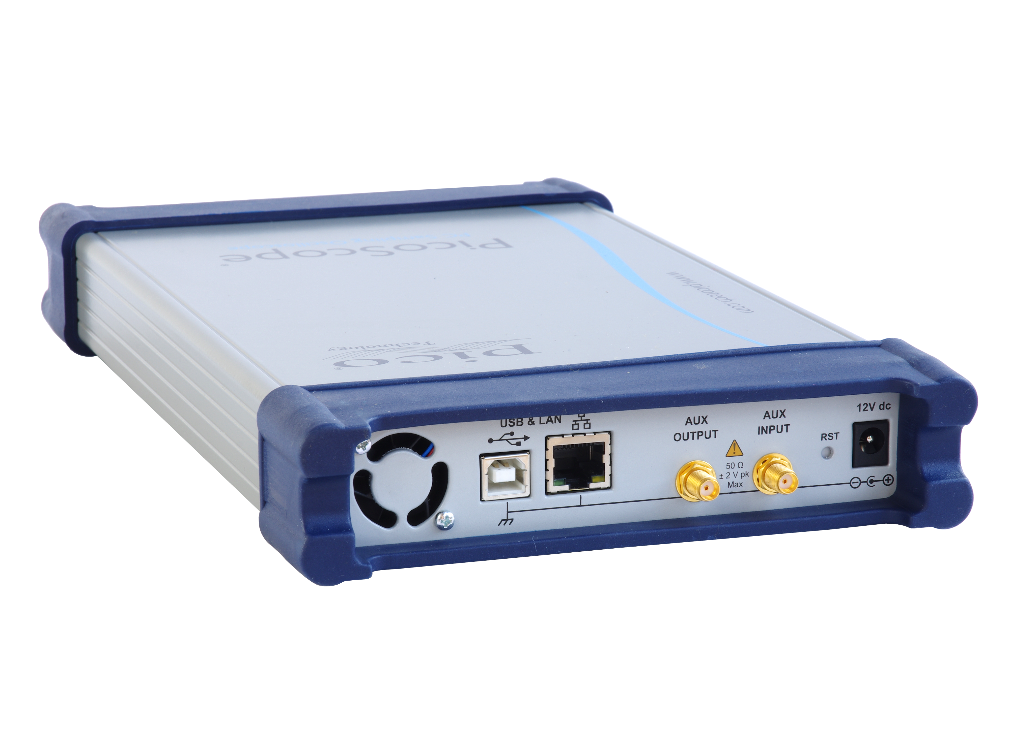
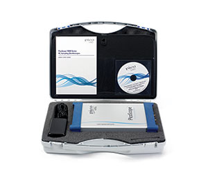
These units occupy very little space on your workbench and are small enough to carry with your laptop for on-site testing, but that’s not all. Instead of using remote probe heads attached to a large bench-top unit, you can position the scope right next to the device under test. Now all that lies between your scope and the DUT is a short, low-loss coaxial cable. Everything you need is built into the oscilloscope, with no expensive hardware or software add-ons to worry about. |
 |
Key specifications
- Bandwidth to 30 GHz
- Two or four channels
- 5 ps/div faster time base
- Less than 1.8 ps rms jitter
- 15 TS/s (64 fs) sequential sampling
- Up to 15 GHz prescaled, 2.5 GHz direct trigger and 11.3 Gb/s clock recovery
- Industry-leading 16-bit 1 MS/s ADC and 60 dB dynamic range
- Eye and mask testing to 16 Gb/s with up to 223–1 pattern lock
- Intuitive, touch-compatible Windows user interface
- Comprehensive built-in measurements, histogramming and editable data mask library
- Integrated, differential, deskewable TDR/TDT step generator
|
 |
Typical applications
- Telecom and radar test, service and manufacturing
- Optical fiber, transceiver and laser testing
- RF, microwave and gigabit digital system measurements
- Radar bands I, G, P, L, S, C, X, Ku
- Precision timing and phase analysis
- Digital system design and characterization
- Eye diagram, mask and limits test to 10 Gb/s
- Ethernet, HDMI 1, HDMI 2, PCI, SATA, USB 2.0, USB 3.0
- TDR/TDT analysis of cables, connectors, backplanes, PCBs and networks
- Optical fiber, transceiver and laser test
- Semiconductor characterization
|
 |
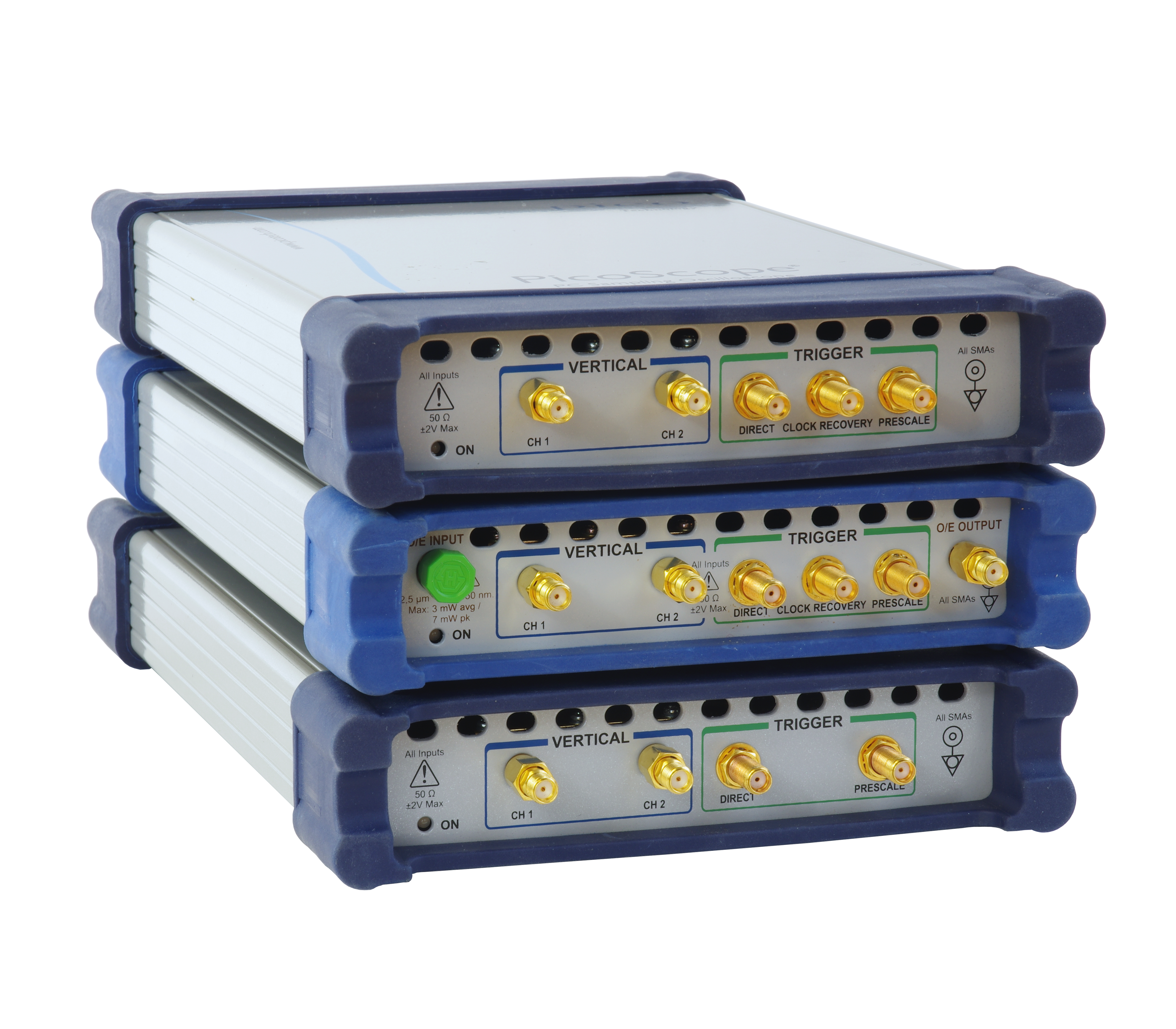
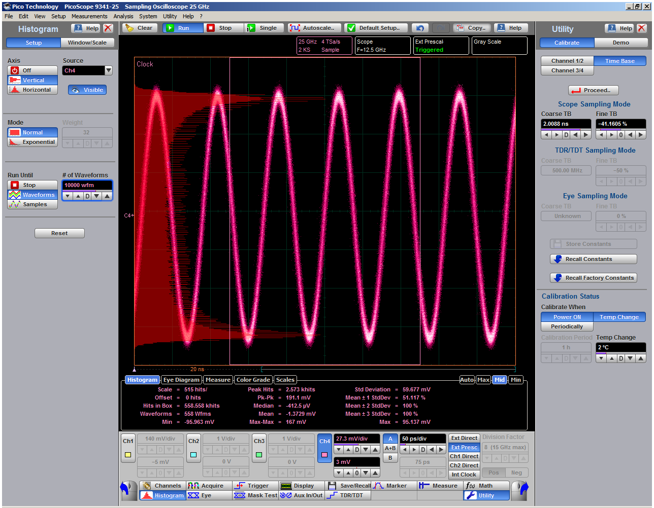
25 GHz bandwidth in a compact USB instrument
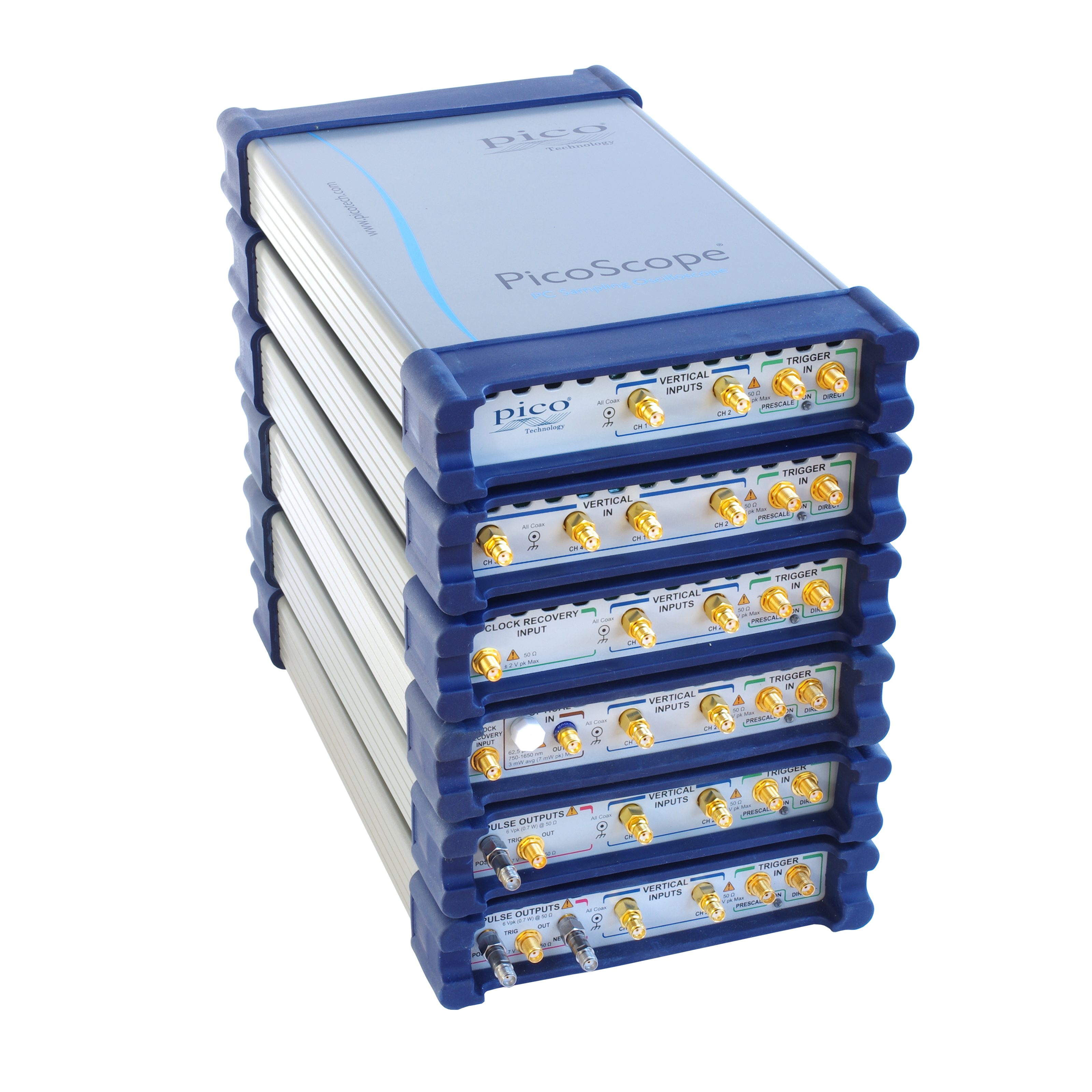
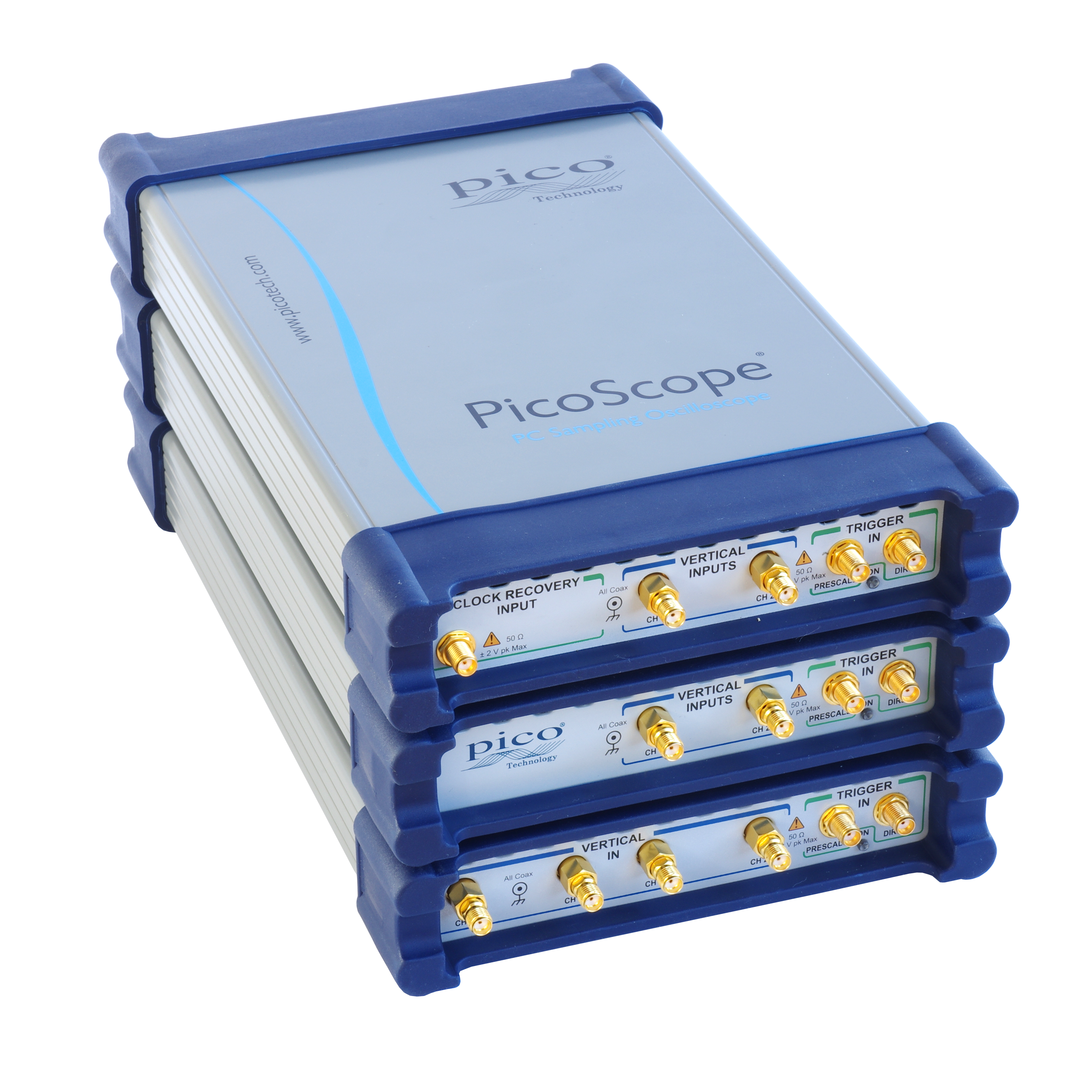
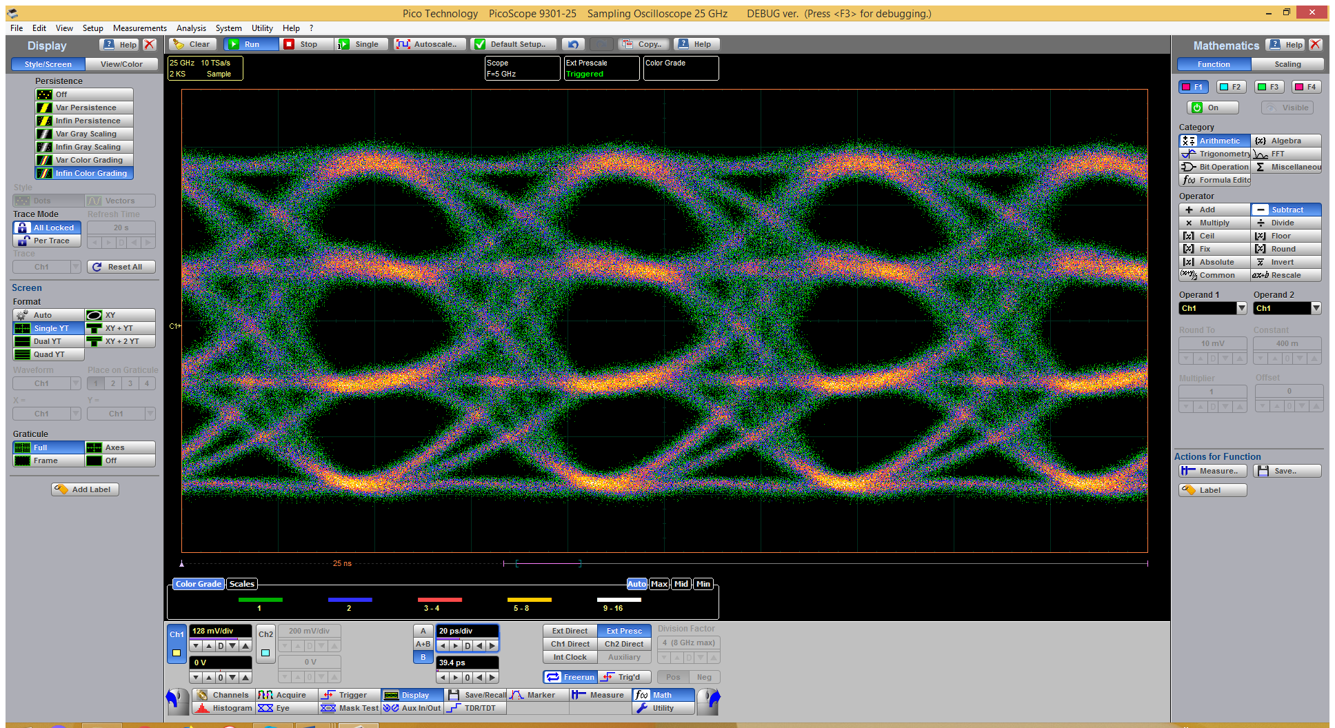
| PicoScope 9300 Series sampling oscilloscopes use triggered sequential sampling to capture high-bandwidth repetitive or clock-derived signals without the expense or jitter of a very high-speed clocked sampling system such as a real-time oscilloscope. 25 GHz bandwidth allows measurement of 14 ps transitions, and low sampling jitter enables timing resolution down to 0.064 ps. Sequential sampling rate of 1 MS/s, unsurpassed by other sampling oscilloscopes, enables rapid building of waveforms, eye diagrams and histograms.
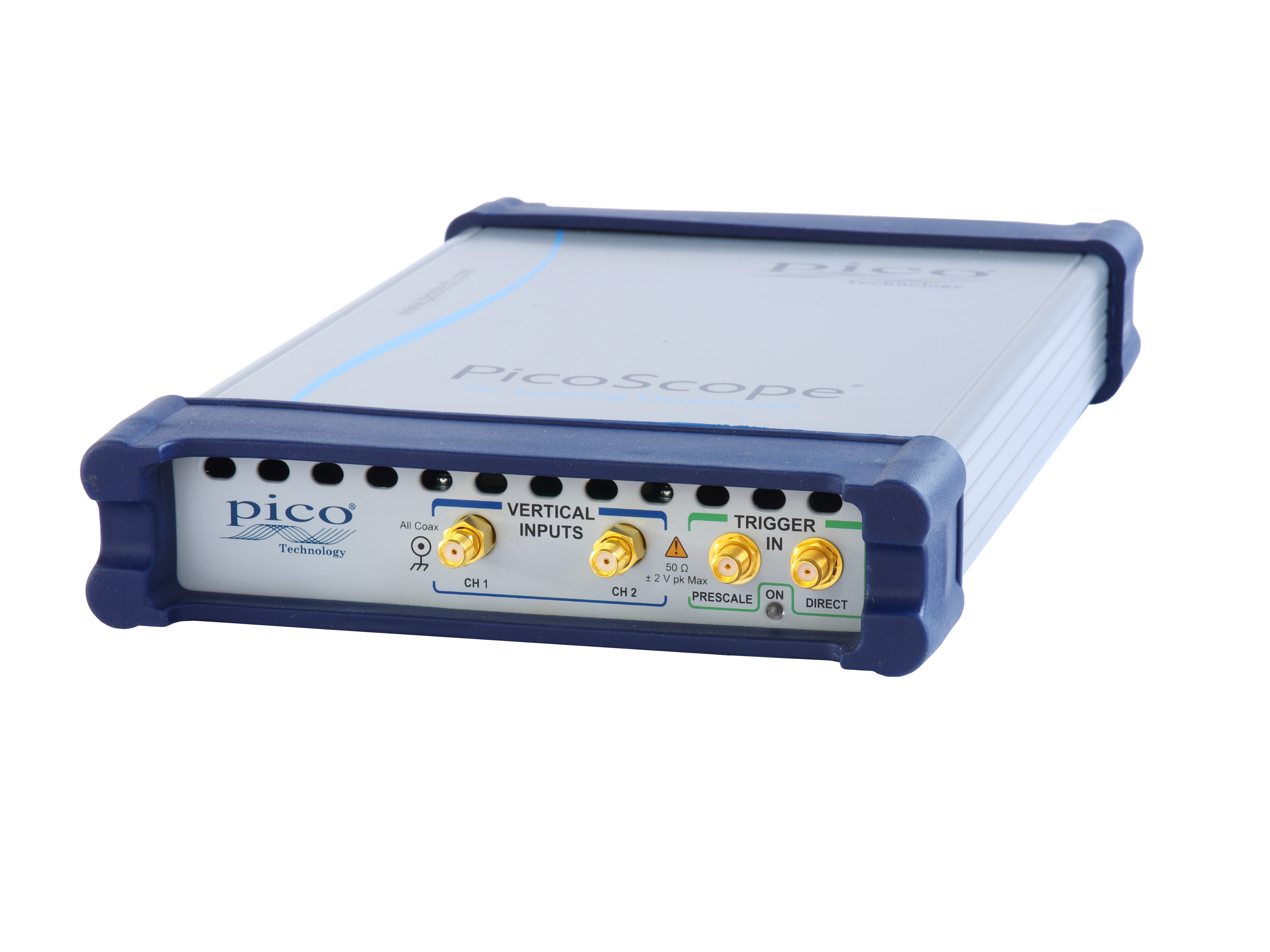
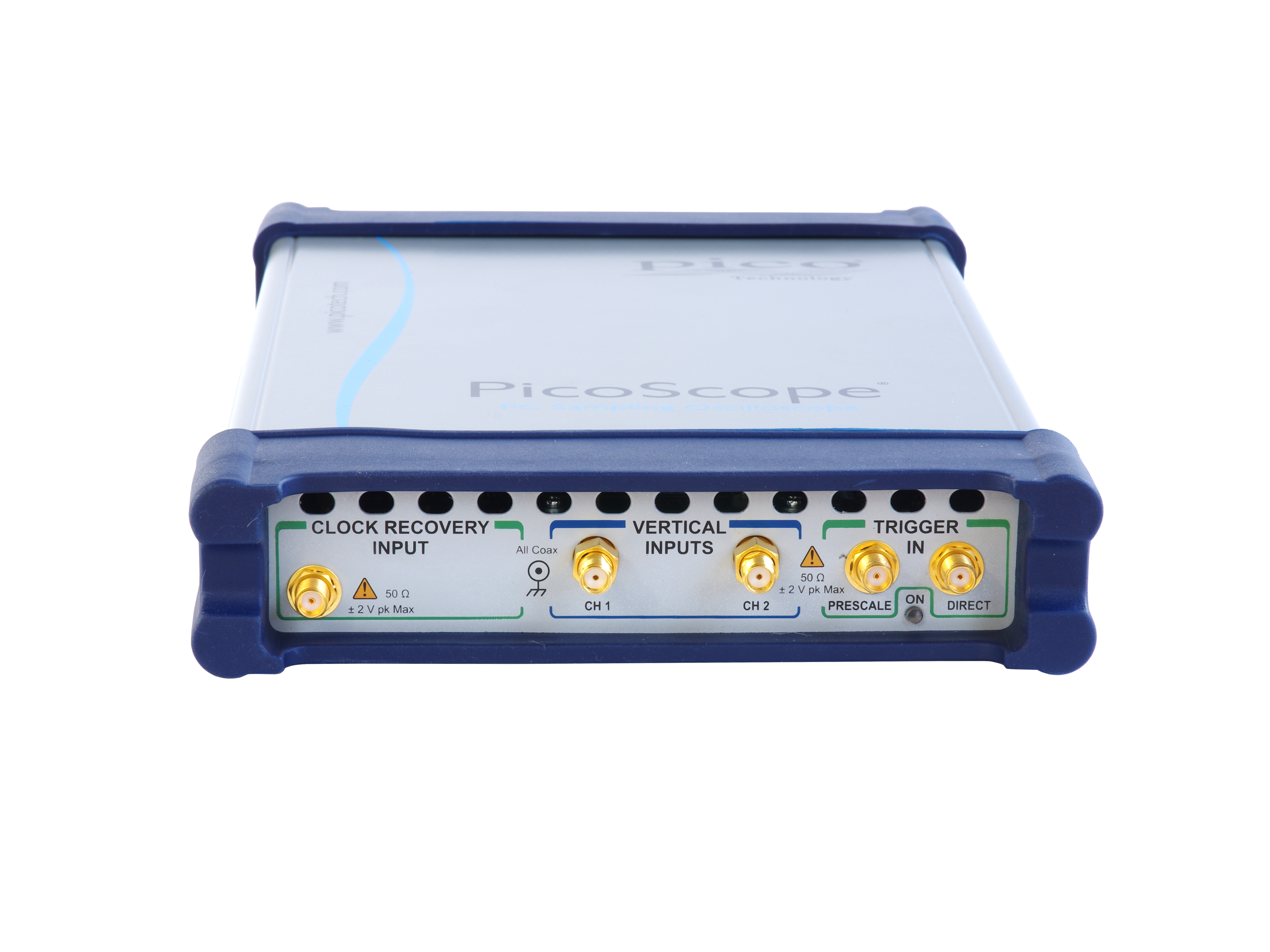
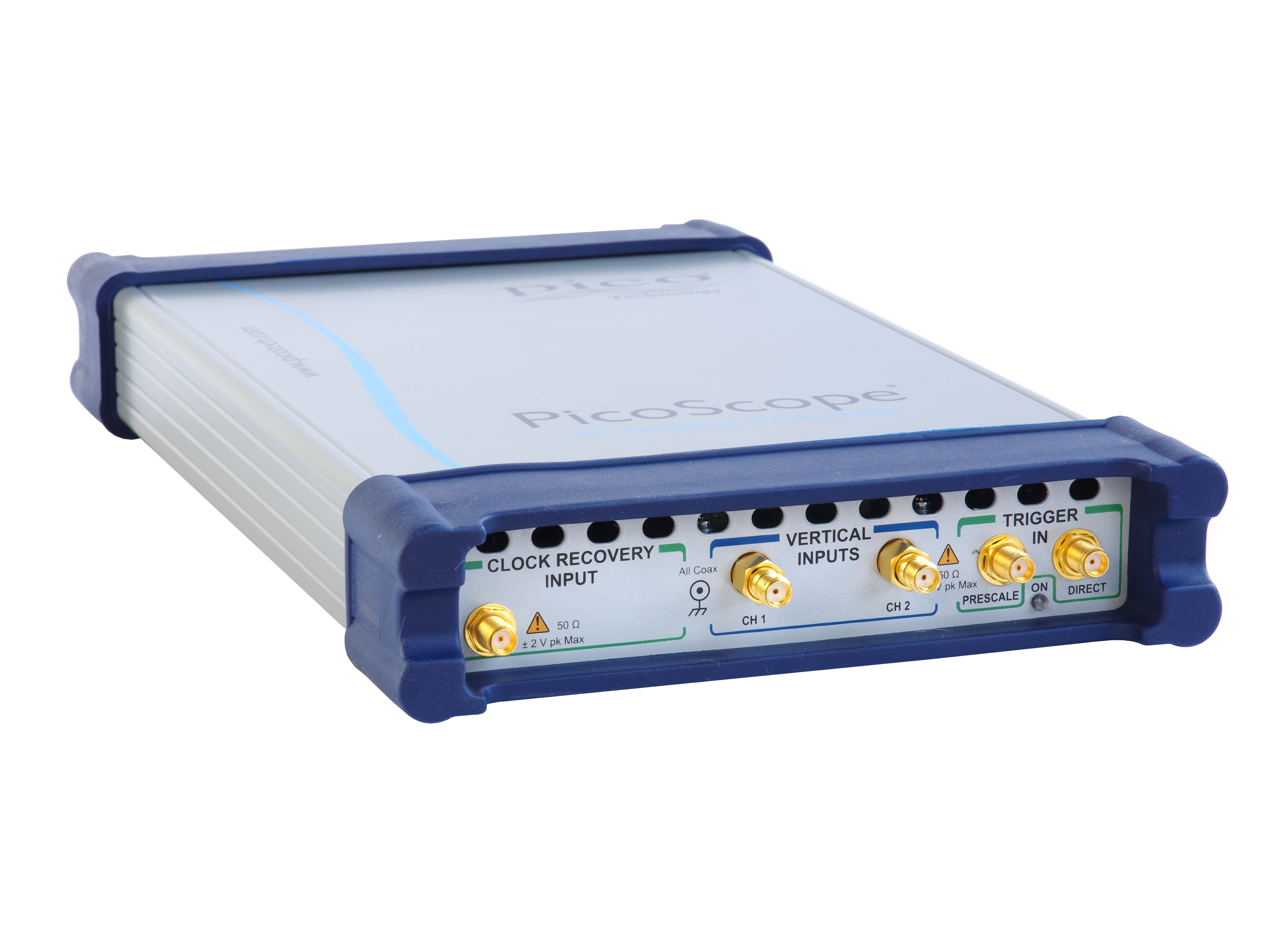
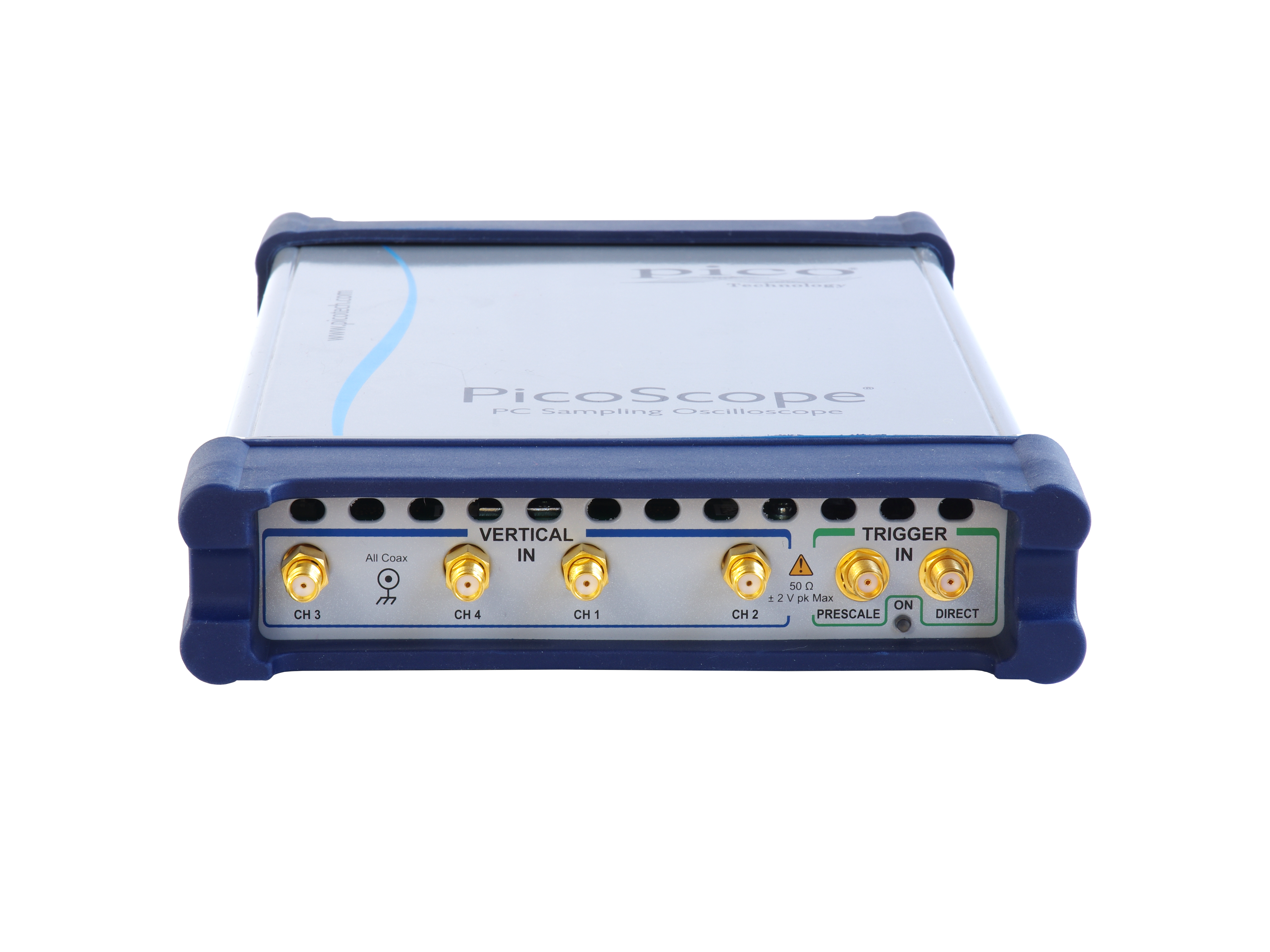
These two and four channel units occupy very little space on a workbench and are small enough to carry with a laptop for on-site testing. Furthermore, instead of using remote probe heads attached to a large bench-top unit, you can position the PicoScope 9300 right next to the device under test and connect to it with short, low-loss coaxial cables.
Everything you need is built into the oscilloscope, with no expensive hardware or software add-ons to worry about. Alternatively, you can use your PicoScope 9300 with a stand-alone PG900 TDR/TDT differential fast pulse generator to gain the extra versatility and configurability of independent high-performance source and measurement instruments.
Watch video – PicoScope 9300 introduction |
 |
Trigger modes
2.5 GHz direct and up to 15 GHz prescaled trigger
Sampling oscilloscopes accept their trigger from a separate input, either directly for repetition rates up to 2.5 GHz or via a prescaling divider input, for repetition rates up to 15 GHz (14 GHz on 15 and 20 GHz models). |
 |
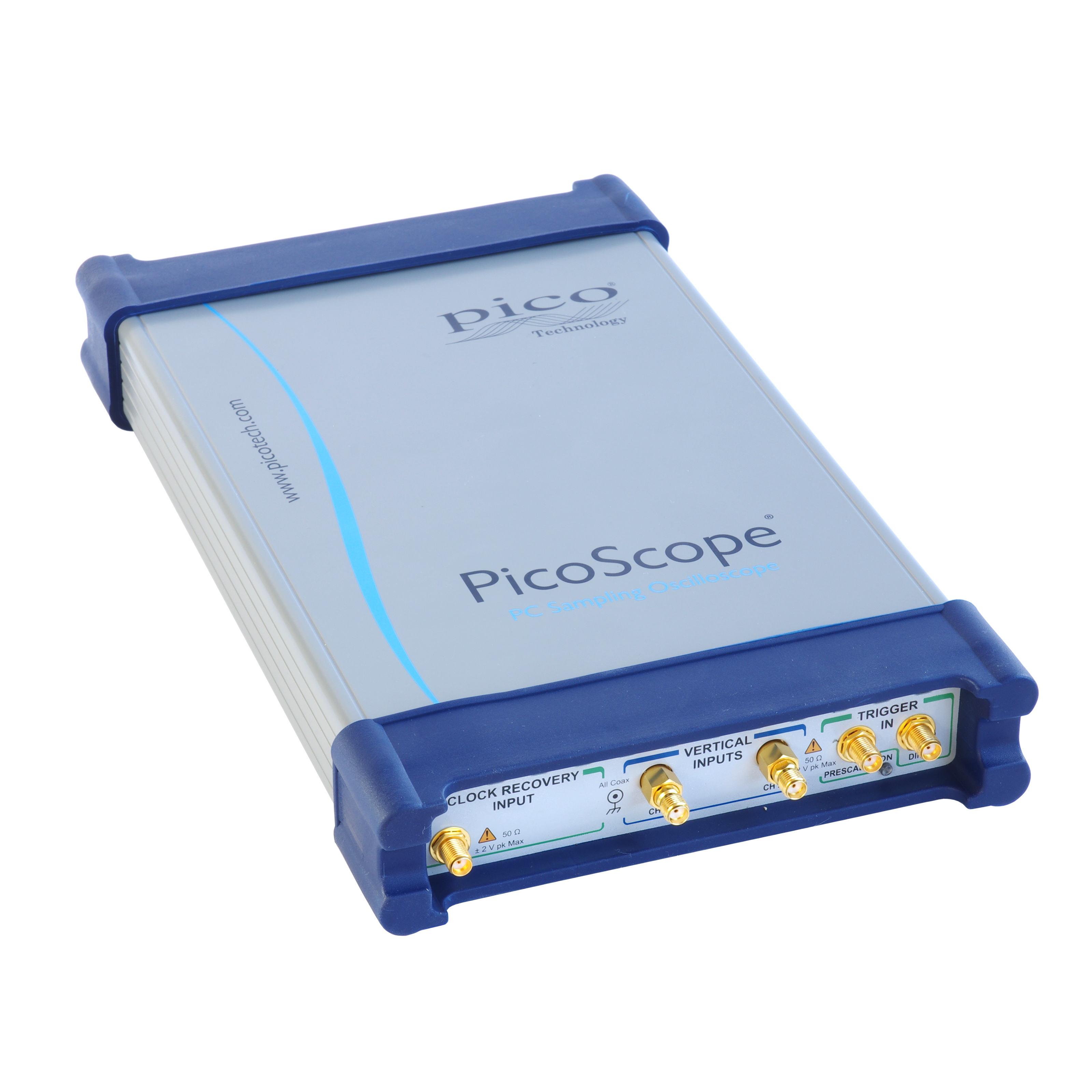
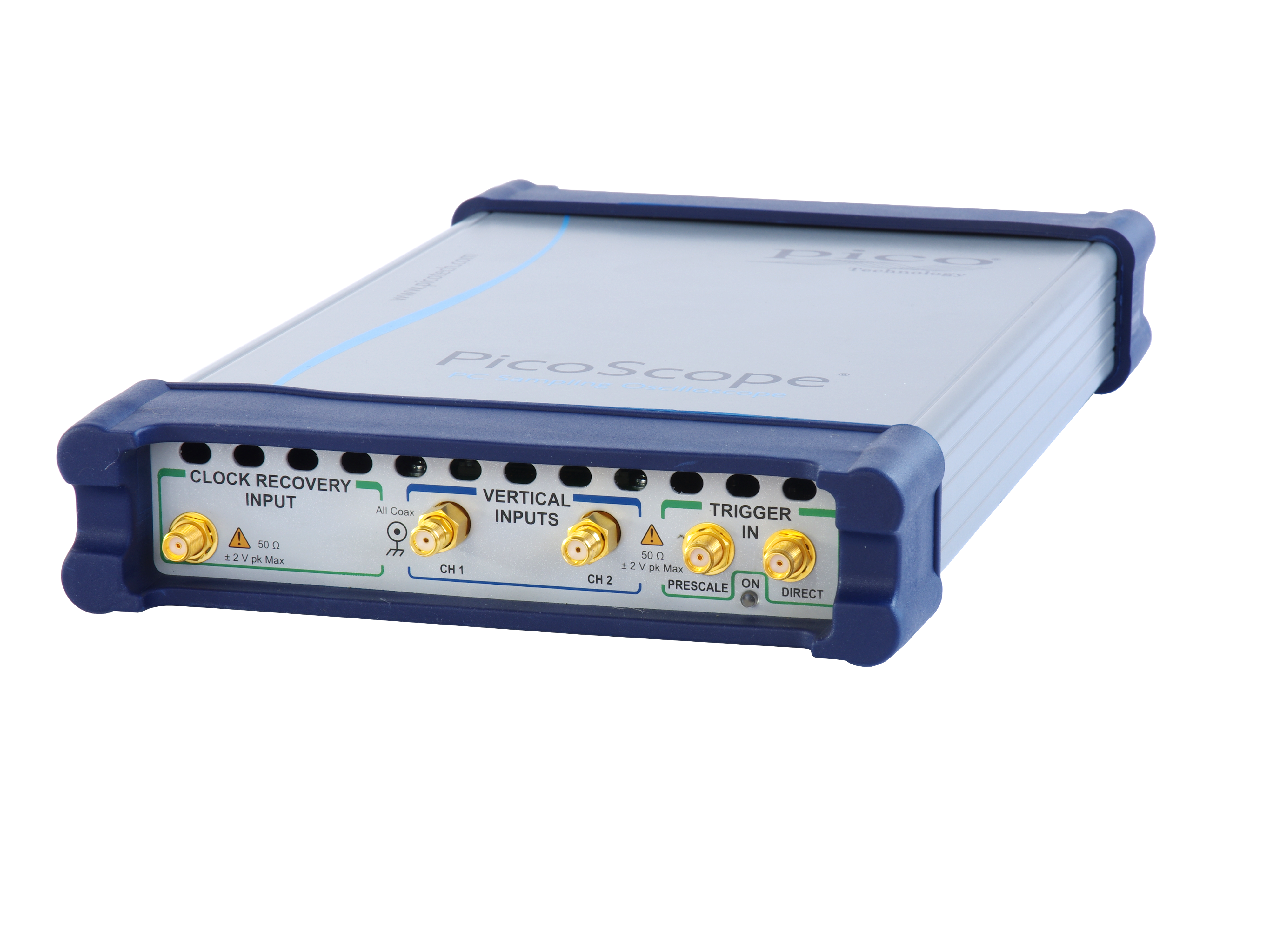
Built-in 11.3 Gb/s clock data recovery trigger
To support serial data applications in which the data clock is not available as a trigger, or for which trigger jitter needs to be reduced, the PicoScope 9302 and 9321 include a clock recovery module. This continuously regenerates the data clock from the incoming serial data or trigger signal and can do so with reduced jitter even over very long trigger delays or for pattern lock applications. A divider accessory kit is included to route the signal to both the clock recovery and oscilloscope inputs |
 |
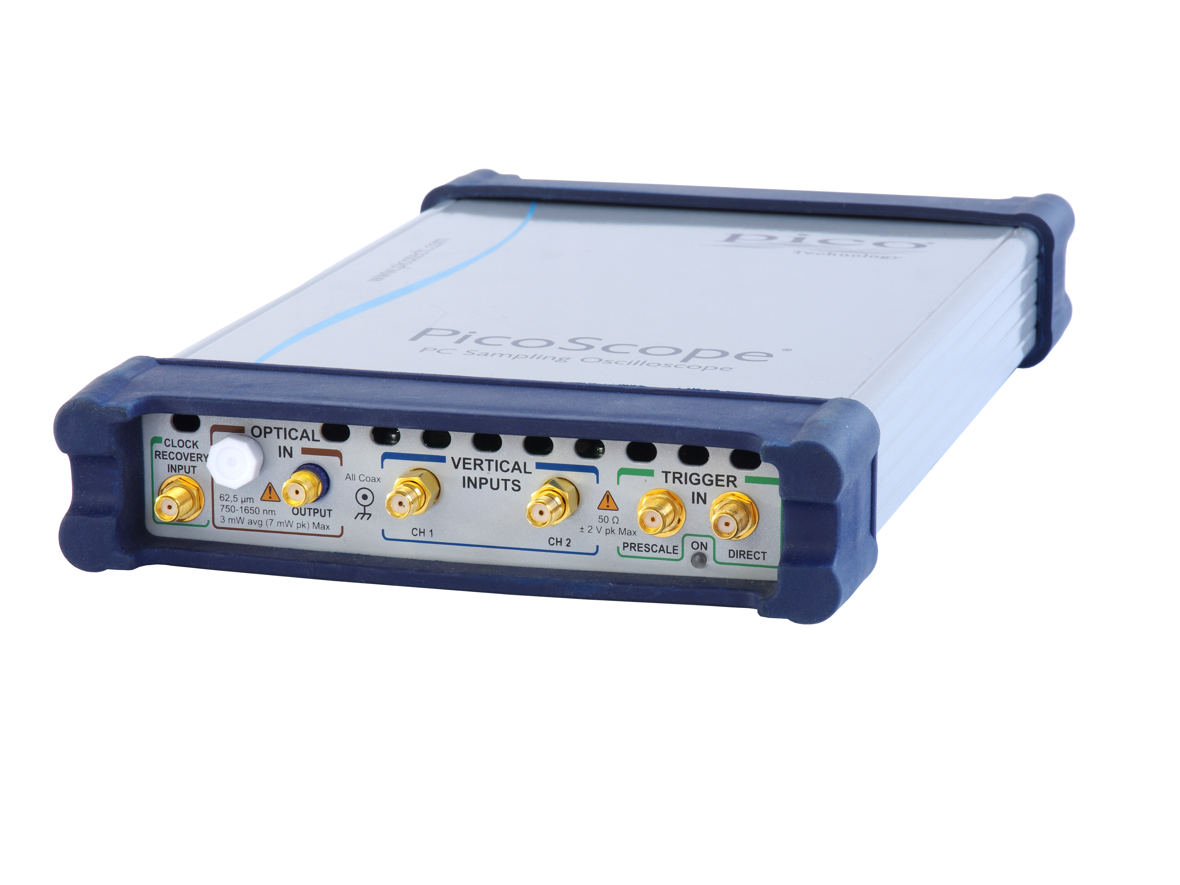
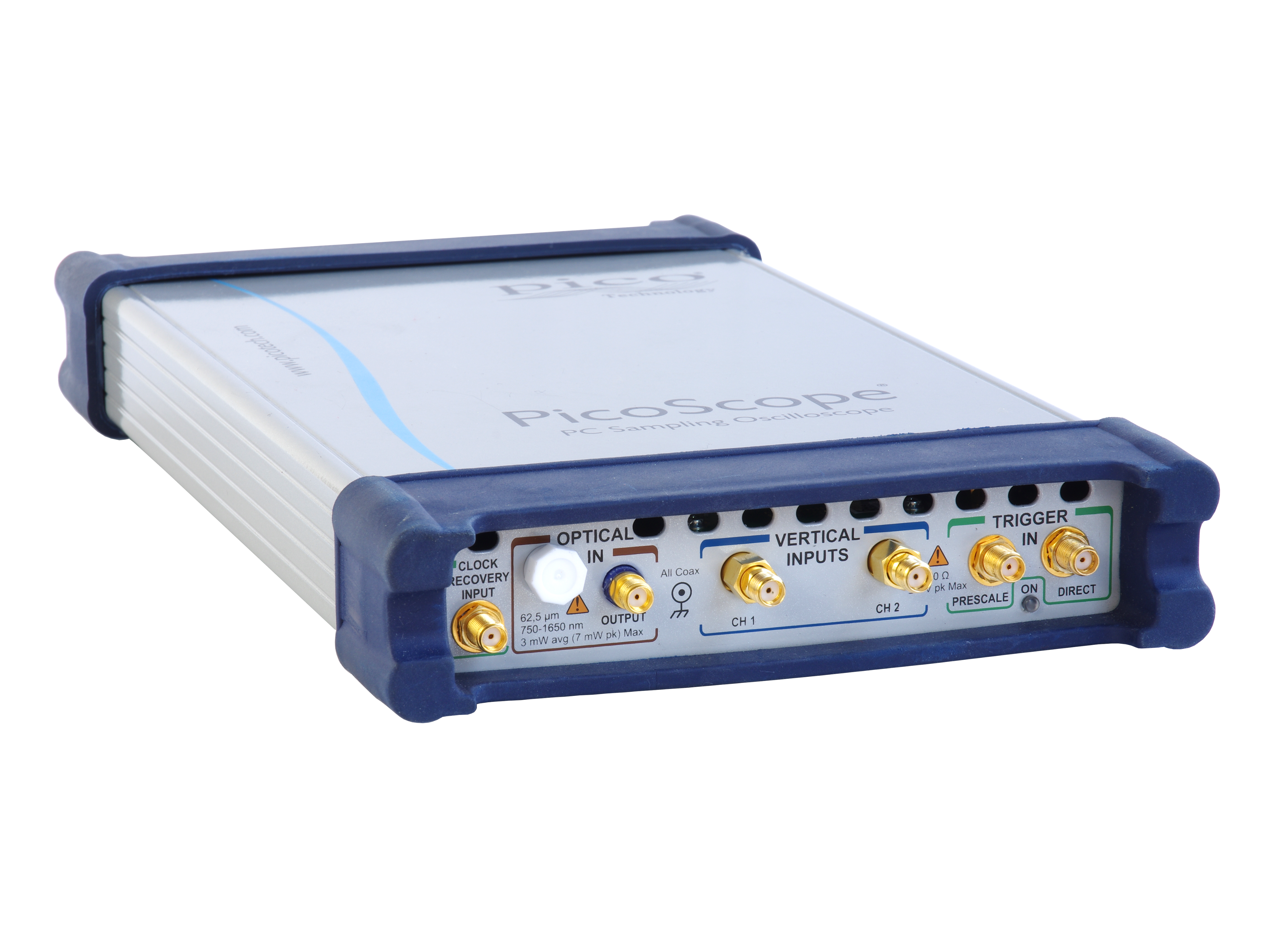
9.5 GHz optical model
The PicoScope 9321-20 includes a built-in precision optical-to-electrical
converter. With the converter output routed to one of the scope inputs
(optionally through an SMA pulse shaping filter), the PicoScope 9321-20 can analyze standard optical communications signals such as OC48/STM16, 4.250 Gb/s Fibre Channel and 2xGB Ethernet. The scope can perform eyediagram measurements with automatic measurement of optical parameters including extinction ratio, S/N ratio, eye height and eye width. With its integrated clock recovery module, the scope is usable to 11.3 Gb/s.
The converter input accepts both single-mode (SM) and multi-mode (MM)
fibers and has a wavelength range of 750 to 1650 nm. |
 |
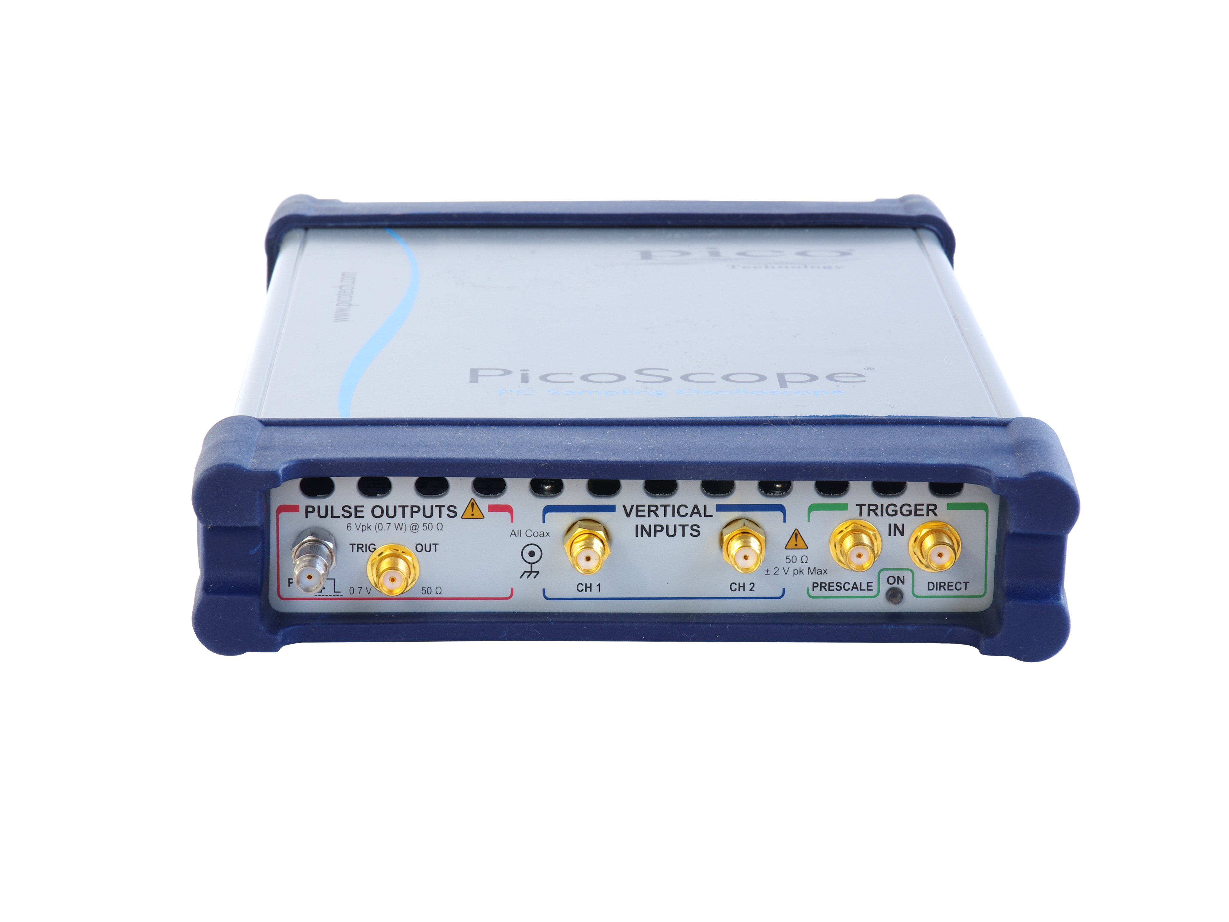
TDR/TDT analysis
The PicoScope 9311 oscilloscopes feature built-in step generators for time-domain reflectometry and transmission measurements. The 9311-15 integrates a single rising step generator suited to single-ended TDR/TDT applications, while the 9311‑20 features deskewable rising and falling step generators suited to single-ended and differential measurements. These features can be used to characterize transmission lines, printed circuit traces, connectors and cables with 16 mm resolution for impedance measurements and 4 mm resolution for fault detection. |
 |
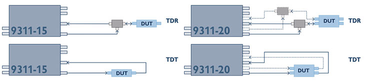
The PicoScope 9311-15 and 9311-20 generate 2.5 to 7 V steps with 60 ps rise time from built-in step recovery diodes. They are supplied with a comprehensive set of calibrated accessories to support your TDR/TDT measurements, including cables, signal dividers, adaptors, attenuator and reference load and short.
The PicoScope 9311-20 TDR/TDT model includes source deskew with 1 ps resolution and comprehensive calibration, reference plane and measurement functions. Voltage, impedance or reflection coefficient (ρ) can be plotted against time or distance.
An alternative approach to TDR/TDT capability is to pair any 9300 Series scope with a standalone PG900 pulse generator. These instruments include similar differential step recovery diode step generators and also offer an option of 40 ps tunnel diode step generation. This brings extra flexibility and the ability to remotely position the pulse source. The generators also enable TDT and TDR with the PicoScope 9301, 9302 clock recovery, 9321 optical and 9341 4-channel sampling oscilloscopes.
Built-in signal generator
|
|
| All the PicoScope 9300 Series scopes can generate industry-standard and custom signals including clock, pulse and pseudo-random binary sequence. You can use these to test the instrument’s inputs, experiment with its features and verify complex setups such as mask tests. AUX OUTPUT can also be configured as a trigger output. |
 |
PicoConnect® 900 Series: the shape of probes to come
The PicoConnect 900 Series is a range of low-invasive, high-frequency passive probes, designed for microwave and gigabit applications up to 9 GHz and 18 Gb/s. They deliver unprecedented performance and flexibility at a low price and are an obvious choice to use alongside the PicoScope 9300 Series scopes. |
 |
Features of the PicoConnect 900 Series probes
- Extremely low loading capacitance of < 0.3 pF typical, 0.4 pF upper test limit for all models
- Slim, fingertip design for accurate and steady probing or solder-in at fine scale
- Interchangeable SMA probe heads at division ratios of 5:1, 10:1 and 20:1, AC or DC coupled
- Accurate probing of high speed transmission lines for Z0 = 0 Ω to 100 Ω
- Class-leading uncorrected pulse/eye response and pulse/eye disturbance
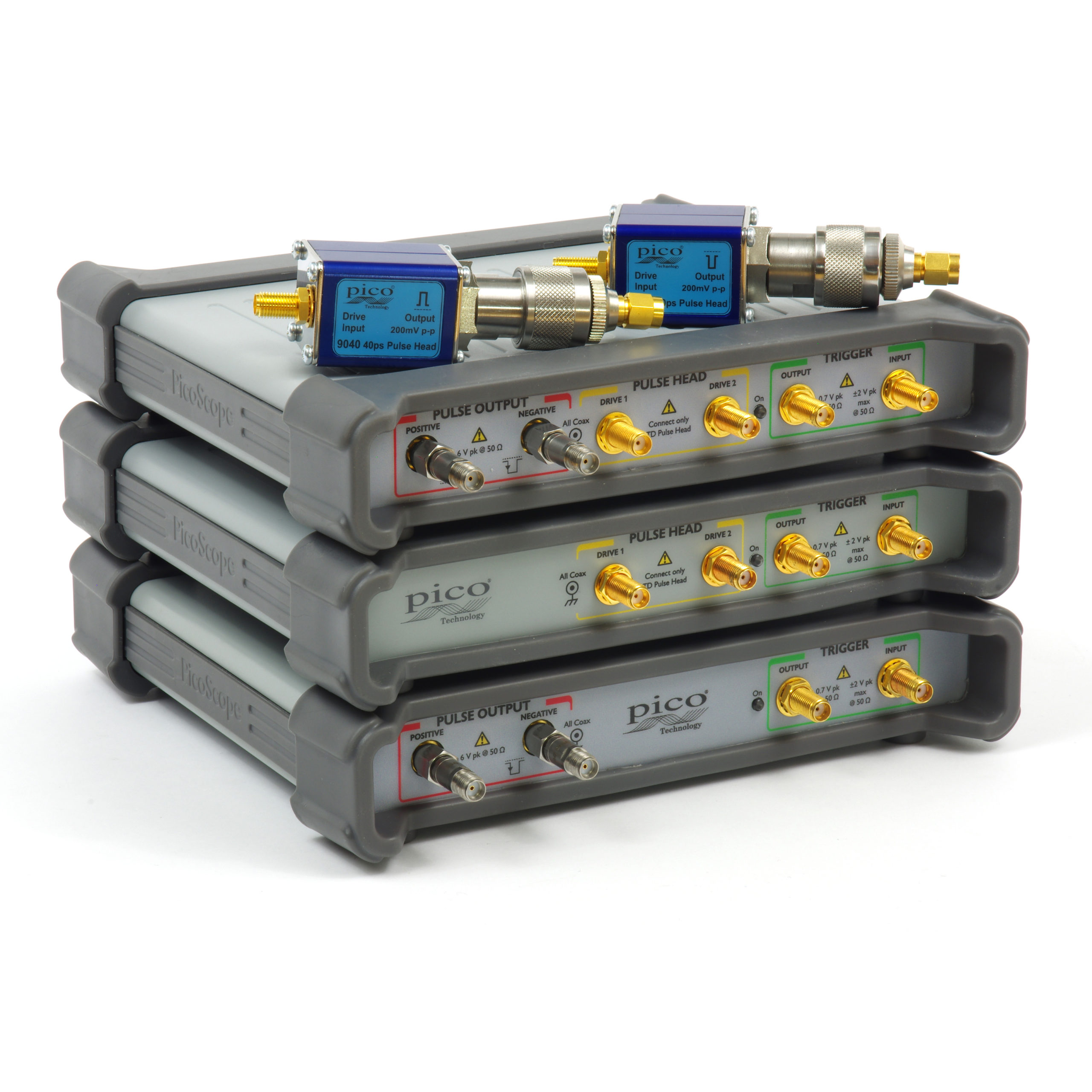
PicoSource® PG900 Series differential pulse generators
For greater versatility than a built-in signal generator can offer, you may want to separate your high-performance fast-step TDR/TDT pulse source from the sampling oscilloscope and have two instruments to use either stand-alone or together as required.
The PicoSource PG900 Series generators contain the same step recovery diode pulse source as the PicoScope 9311, or slightly faster but reduced amplitude tunnel diode pulse heads, rehoused in a separate USB-controlled instrument. All are supplied with PicoSource PG900 control software. |
 |
PicoSource® PG900 Series differential pulse generators
|
|
|
For greater versatility than a built-in signal generator can offer, you may want to separate your high-performance fast-step TDR/TDT pulse source from the sampling oscilloscope and have two instruments to use either stand-alone or together as required.
The PicoSource PG900 Series generators contain the same step recovery diode pulse source as the PicoScope 9311, or slightly faster but reduced amplitude tunnel diode pulse heads, rehoused in a separate USB-controlled instrument. All are supplied with PicoSource PG900 control software.
|
|
SMA Bessel-Thomson pulse-shaping filters
For use with the 9321-20 optical to electrical converter, a range of Bessel–Thomson filters is available for standard bit rates. These filters are essential for accurate characterization of signals emerging from an optical transmission system. |
 |
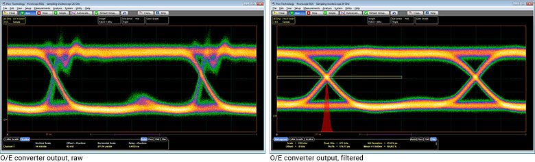
The first eye diagram, above left, shows the ringing typical of an unequalized O/E converter output at 622 Mb/s. The second eye diagram, above right, shows the result of connecting the 622 Mb/s B-T filter. This is an accurate representation of the signal that an equalized optical receiver would see, enabling the PicoScope 9321 to display correct measurements.
Product videos
Introduction to the
PicoScope 9300
Sampling
Oscilloscope
|
PicoScope 9300 Sampling Oscilloscopes
and PG900 Fast Pulse
Generators
|
Time Domain Reflectometry
using PicoScope 9300 Series Oscilloscopes
|
Application-configurable PicoSample 3 oscilloscope software
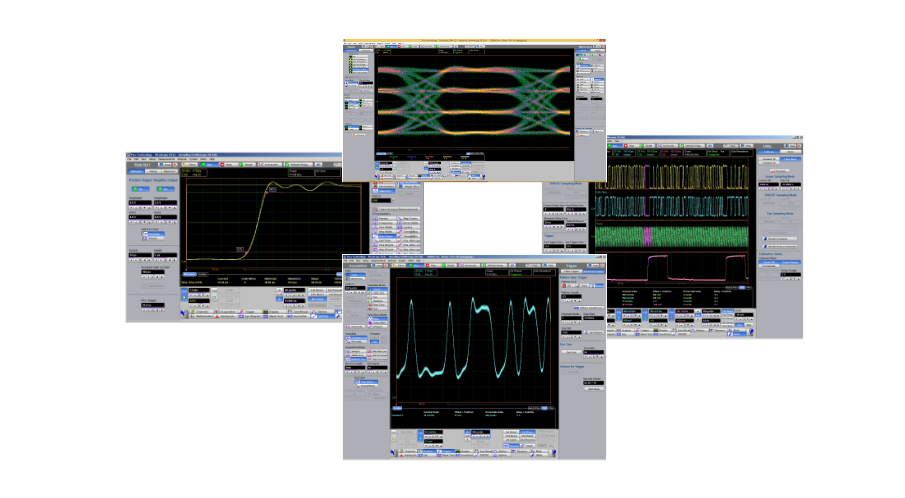
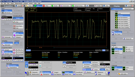
Designed for ease of use
The PicoSample 3 workspace takes full advantage of your available display size and resolution. You decide how much space to give to the trace display and the measurements display, and whether to open or hide the control menus. The user interface is fully touch- or mouse-operable, with grabbing and dragging of traces, cursors, regions and parameters. There are enlarged parameter controls for use on smaller touch displays. To zoom, either draw a zoom window or use the more traditional dual timebase, delay and scaling controls.
A choice of screen formats
When working with multiple traces, you can display them all on one grid or separate them into two or four grids. You can also plot signals in XY mode with or without additional voltage-time grids. The persistence display modes use color-coding or shading to show statistical variations in the signal. Trace display can be in either dots-only or vector format.
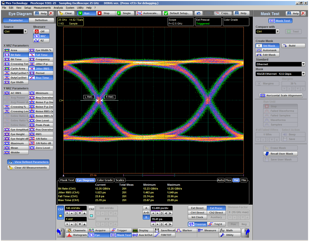
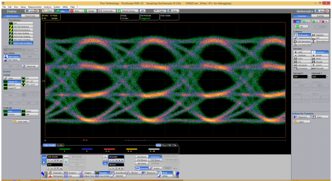
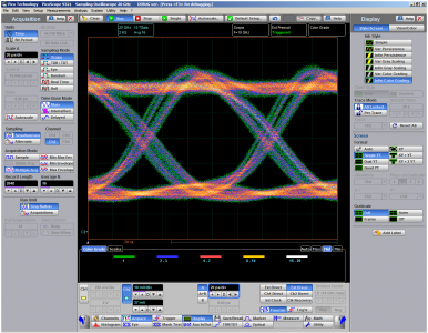
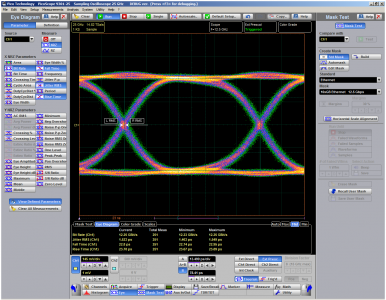
Eye-diagram analysis
The PicoScope 9300 Series scopes quickly measure more than 30 fundamental parameters used to characterize non‑return‑to‑zero (NRZ) signals and return-to-zero (RZ) signals. Up to ten parameters can be measured simultaneously, with comprehensive statistics also shown.
The measurement points and levels used to generate each parameter can optionally be drawn on the trace.
Eye-diagram analysis can be made even more powerful with the addition of mask testing, as described below. |
 |
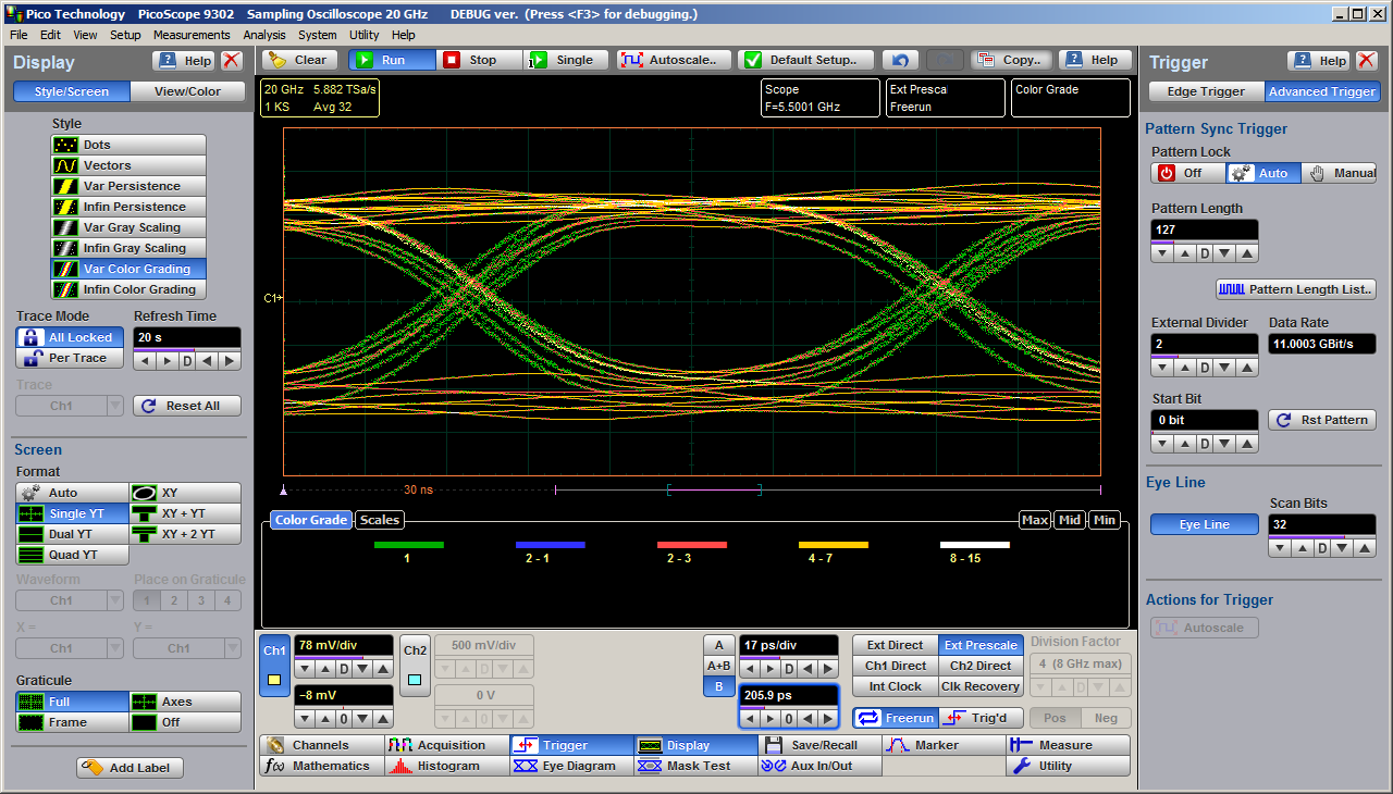
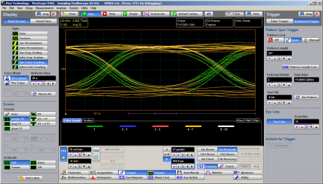
Pattern sync trigger and eye line mode
When a repeating data pattern such as a pseudorandom bit sequence is present, an internal trigger divider can lock to it. You can then use eye-line mode to move the trigger point, and view point, along the whole pattern, bit by bit. Eye-line scan mode is also available to build an eye diagram from a user-selected range of bit intervals through to the whole pattern. These features are useful for analyzing data-dependent waveshapes. |
 |
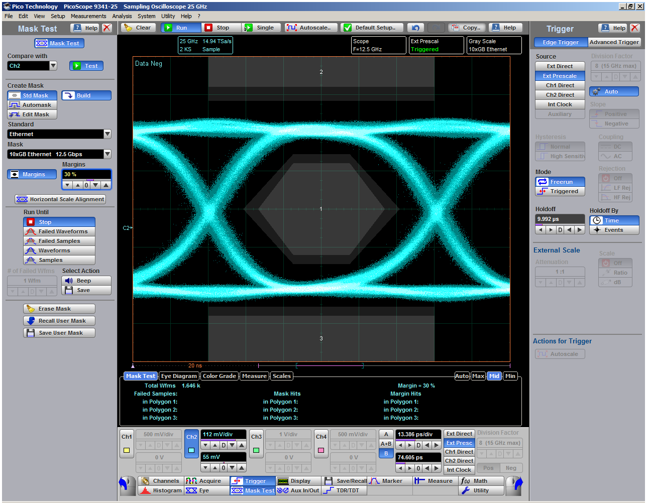
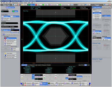
Mask testing
PicoSample 3 has a built-in library of over 160 masks for testing data eyes. It can count or capture mask hits or route them to an alarm or acquisition control. You can stress-test against a mask using a specified margin, and locally compile or edit masks.
There’s a choice of gray-scale and color-graded display modes to aid in analyzing noise and jitter in eye diagrams. There is also a statistical display showing a failure count for both the original mask and the margin.
The extensive menu of built-in test waveforms is invaluable for checking your mask test setup before using it on live signals. |
 |
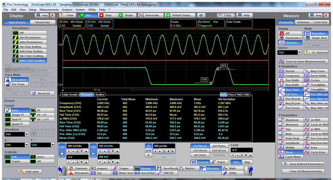
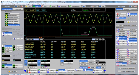
Measurement of over 100 waveform parameters with statistics
The PicoScope 9300 Series scopes quickly measure well over 100 standard waveform and eye parameters, either for the whole waveform or constrained between markers. The markers can also make on-screen ruler measurements, so you don’t need to count graticules or estimate the waveform’s position. Up to ten simultaneous measurements are possible. The measurements conform to IEEE standard definitions, but you can edit them for non-standard thresholds and reference levels using the advanced menu or by dragging the on-screen thresholds and levels. You can apply limit tests to up to four measured parameters.
A dedicated frequency counter shows signal frequency at all times, regardless of measurement and timebase settings. |
 |
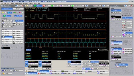
Powerful mathematical analysis
The PicoScope 9300 Series scopes support up to four simultaneous mathematical combinations or functional transformations of acquired waveforms.
You can select any of the mathematical functions to operate on either one or two sources. All functions can operate on live waveforms, waveform memories or even other functions. There is also a comprehensive equation editor for creating custom functions of any combination of source waveforms.
- Choose from 61 math functions, or create your own
- Add, Subtract, Multiply, Divide, Invert, Absolute, Exponent, Logarithm, Differentiate, Integrate, Inverse, FFT, Interpolation, Smoothing
|
 |
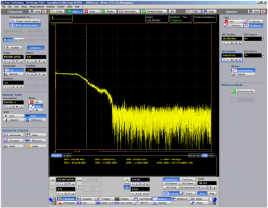
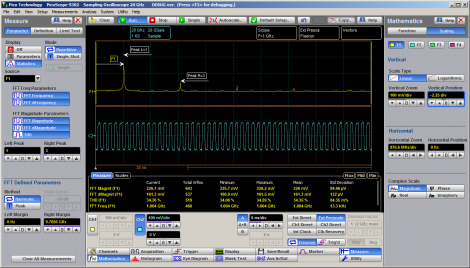
FFT analysis
All PicoScope 9300 Series oscilloscopes can calculate real, imaginary and complex Fast Fourier Transforms of input signals using a range of windowing functions. The results can be further processed using the math functions. FFTs are useful for finding crosstalk and distortion problems, adjusting filter circuits designed to filter out certain harmonics in a waveform, testing impulse responses of systems, and identifying and locating noise and interference sources. |
 |
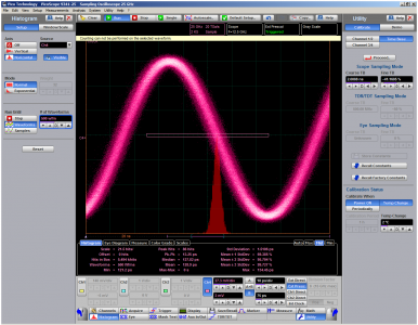
Histogram analysis
Behind the powerful measurement and display capabilities of the 9300 Series lies a fast, efficient data histogramming capability. A powerful visualization and analysis tool in its own right, the histogram is a probability graph that shows the distribution of acquired data from a source within a user-definable window.
Histograms can be constructed on waveforms on either the vertical or horizontal axes. The most common use for a vertical histogram is measuring and characterizing noise and pulse parameters. A horizontal histogram is typically used to measure and characterize jitter. |
 |
Software Development Kit
The PicoSample 3 software can operate as a stand-alone oscilloscope program or under ActiveX remote control. The ActiveX control conforms to the Windows COM interface standard so that you can embed it in your own software. Unlike more complex driver-based programming methods, ActiveX commands are text strings that are easy to create in any programming environment. Programming examples are provided in Visual Basic (VB.NET), MATLAB, LabVIEW and Delphi, but you can use any programming language or standard that supports the COM interface, including JavaScript and C. National Instruments LabVIEW drivers are also available. All the functions of the PicoScope 9300 and the PicoSample software are accessible remotely.
The SDK consists of the PicoSample 3 software download and a comprehensive programmer’s guide, both available from picotech.com, and example code freely available from our GitHub organization page, github.com/picotech. The SDK can control the oscilloscope over the USB or the LAN port. |
 |
Please give us your feedback about PicoScope 9300 Series
Your opinion is very important to us. We appreciate your feedback and will use it to evaluate changes and make improvements in our products:
PicoScope 9300 Series Downloads
Here you can download the latest PicoScope 9300 Series Data Sheets, Manuals, Guides and other relevant documents:
PicoScope 9300 specifications
Here you can check the latest PicoScope 9300 Series specifications:
| Oscilloscope – vertical (analog) |
9300-15 models |
9300-20 models |
9300-25 models |
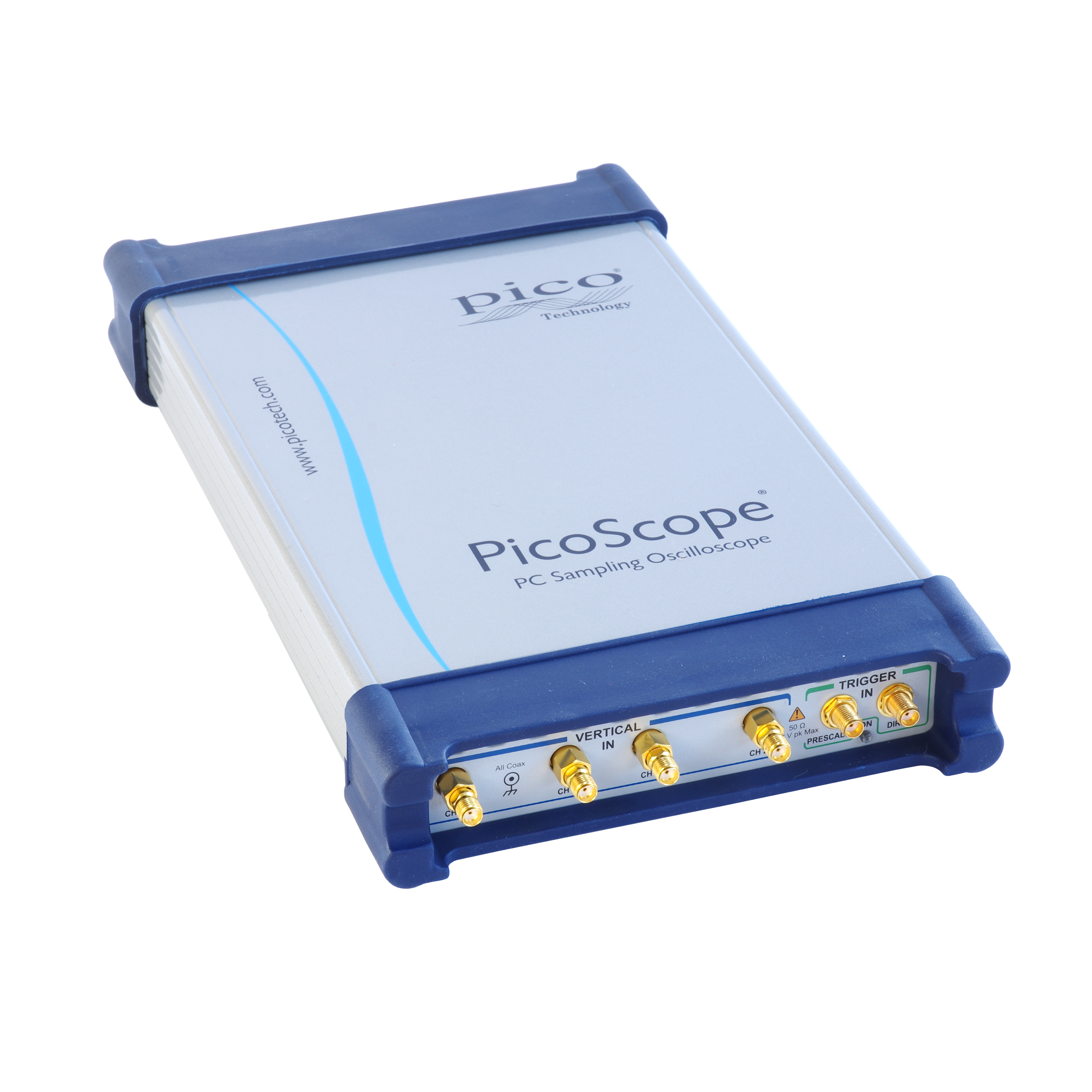
| Number of channels |
PicoScope 9341: 4
All other models: 2 |
| Acquisition timing |
Selectable simultaneous or alternate acquisition |
| Bandwidth, Full |
15 GHz |
20 GHz |
25 GHz |
| Bandwidth, Narrow |
8 GHz |
10 GHz |
12 GHz |
| Pulse response rise time, full bandwidth |
23.4 ps (10% to 90%, calculated) |
17.5 ps (10% to 90%, calculated) |
14.0 ps (10% to 90%, calculated) |
| Pulse response rise time, narrow bandwidth |
43.8 ps (10% to 90%, calculated) |
35.0 ps (10% to 90%, calculated) |
29.2 ps (10% to 90%, calculated) |
| Noise, full bandwidth |
< 1.2 mV RMS typical, < 1.6 mV RMS maximum |
< 1.5 mV RMS typical, < 2.0 mV RMS maximum |
< 1.9 mV RMS typical, < 2.5 mV RMS maximum |
| Noise, narrow bandwidth |
< 0.7 mV RMS typical, < 0.9 mV RMS maximum |
< 0.8 mV RMS typical, < 1.1 mV RMS maximum |
< 1.0 mV RMS typical, < 1.3 mV RMS maximum |
| Noise with averaging |
100 μV RMS system limit, typical |
| Operating input voltage with digital feedback |
1 V p-p with ±1 V range (single-valued) |
| Operating input voltage without digital feedback |
±400 mV relative to channel offset (multi-valued) |
| Sensitivity |
1 mV/div to 500 mV/div in 1-2-5 sequence with 0.5% fine increments |
| Resolution |
16 bits, 40 μV/LSB |
| Accuracy |
±2% of full scale ±2 mV over nominal temperature range (assuming temperature-related calibrations are performed) |
| Nominal input impedance |
(50 ±1) Ω |
| Input connectors |
2.92 mm (K) female, compatible with SMA and PC3.5 |
| Timebase (Sequential time sampling mode) |
| Ranges |
5 ps/div to 3.2 ms/div (main, intensified, delayed, or dual delayed) |
| Delta time interval accuracy |
For > 200 ps/div: ±0.2% of delta time interval ± 12 ps
For < 200 ps/div: ±5% of delta time interval ± 5 ps |
| Time interval resolution |
64 fs |
| Channel deskew |
1 ps resolution, 100 ns max. |
| Triggers |
| Trigger sources |
All models: external direct, external prescaled, internal direct and internal clock triggers.
PicoScope 9302 and 9321 only: external clock recovery trigger |
| External direct trigger bandwidth and sensitivity |
DC to 100 MHz : 100 mV p-p; to 2.5 GHz: 200 mV p-p |
| External direct trigger jitter |
1.8 ps RMS (typ.) or 2.0 ps RMS (max.) + 20 ppm of delay setting |
| Internal direct trigger bandwidth and sensitivity |
DC to 10 MHz: 100 mV p-p; to 100 MHz: 400 mV p-p (channels 1 and 2 only) |
| Internal direct trigger jitter |
25 ps RMS (typ.) or 30 ps RMS (max.) + 20 ppm of delay setting (channels 1 and 2 only) |
| External prescaled trigger bandwidth and sensitivity |
1 to 14 GHz, 200 mV p-p to 2 V p-p |
1 to 14 GHz, 200 mV p-p to 2 V p-p
14 to 15 GHz, 500 mV p-p to 2 V p-p |
| External prescaled trigger jitter |
1.8 ps RMS (typ.) or 2.0 ps RMS (max.) + 20 ppm of delay setting |
| Pattern sync trigger clock frequency |
10 MHz to 14 GHz |
10 MHz to 14 GHz |
10 MHz to 15 GHz |
| Pattern sync trigger pattern length |
7 to 8 388 607 (223− 1) |
| Clock recovery (PicoScope 9302 and 9321) |
| Clock recovery trigger data rate and sensitivity |
6.5 Mb/s to 100 Mb/s: 100 mV p-p
>100 Mb/s to 11.3 Gb/s: 20 mV p-p |
| Recovered clock trigger jitter |
1 ps (typ.) or 1.5 ps (max.) + 1.0% of unit interval |
| Maximum safe trigger input voltage |
±2 V (DC + peak AC) |
| Input characteristics |
50 Ω, AC coupled |
| Input connector |
SMA (F) |
| Acquisition |
| ADC resolution |
16 bits |
| Digitizing rate with digital feedback (single-valued) |
DC to 1 MHz |
| Digitizing rate without digital feedback (multi-valued) |
DC to 40 kHz |
| Acquisition modes |
Sample (normal), average, envelope |
| Data record length |
32 to 32 768 points (single channel) in x2 sequence |
| Display |
| Styles |
Dots, vectors, persistence, gray-scaling, color-grading |
| Persistence time |
Variable or infinite |
| Screen formats |
Auto, single YT, dual YT, quad YT, XY, XY + YT, XY + 2 YT |
| Measurement and analysis |
| Markers |
Vertical bars, horizontal bars (measure volts) or waveform markers |
| Automatic measurements |
Up to 10 at once |
| Measurements, X parameters |
Period, frequency, pos/neg width, rise/fall time, pos/neg duty cycle, pos/neg crossing, burst width, cycles, time at max/min, pos/neg jitter ppm/RMS |
| Measurements, Y parameters |
Max, min, top, base, peak-peak, amplitude, middle, mean, cycle mean, AC/DC RMS, cycle AC/DC RMS, pos/neg overshoot, area, cycle area |
| Measurements, trace-to-trace |
Delay 1R-1R, delay 1F-1R, delay 1R-nR, delay 1F-nR, delay 1R-1F, delay 1F-1F, delay 1R-nF, delay 1F-nF, phase deg/rad/%, gain, gain dB |
| Eye measurements, X NRZ |
Area, bit rate, bit time, crossing time, cycle area, duty cycle distortion abs/%, eye width abs/%, rise/fall time, frequency, period, jitter p-p/RMS |
| Eye measurements, Y NRZ |
AC RMS, average power lin/dB, crossing %/level, extinction ratio dB/%/lin, eye amplitude, eye height lin/dB, max/min, mean, middle, pos/neg overshoot, noise p-p/RMS one/zero level, p-p, RMS, S/N ratio lin/dB |
| Eye measurements, X RZ |
Area, bit rate/time, cycle area, eye width abs/%, rise/fall time, jitter p-p/RMS fall/rise, neg/pos crossing, pos duty cycle, pulse symmetry, pulse width |
| Eye measurements, Y RZ |
AC RMS, average power lin/dB, contrast ratio lin/dB/%, extinction ratio lin/dB/%, eye amplitude, eye high lin/dB, eye opening, max, min, mean, middle, noise p-p/RMS one/zero, one/zero level, peak-peak, RMS, S/N |
| Histogram |
Vertical or horizontal |
| Math functions |
| Mathematics |
Up to four math waveforms can be defined and displayed |
| Math functions, arithmetic |
+, −, ×, ÷, ceiling, floor, fix, round, absolute, invert, (x+y)/2, ax+b |
| Math functions, algebraic |
ex, ln, 10x, log10, ax, loga, d/dx, integrate, x2, sqrt, x3, xa, x−1, sqrt(x2 +y2) |
| Math functions, trigonometric |
sin, sin−1, cos, cos−1, tan, tan−1, cot, cot−1, sinh, cosh, tanh, coth |
| Math functions, FFT |
Complex FFT, complex inverse FFT, magnitude, phase, real, imaginary |
| Math functions, combinatorial logic |
AND, NAND, OR, NOR, XOR, XNOR, NOT |
| Math functions, interpolation |
Linear, sin(x)/x, trend, smoothing |
| Math functions, other |
Custom formula |
| FFT |
Up to two FFTs simultaneously |
| FFT window functions |
Rectangular, Hamming, Hann, flat-top, Blackman–Harris, Kaiser–Bessel |
| Eye diagram |
Automatically characterizes NRZ and RZ eye patterns based on statistical analysis of waveform |
| Mask tests |
| Mask geometry |
Acquired signals are tested for fit outside areas defined by up to eight polygons. Standard or user-defined masks can be selected. |
| Built-in masks, SONET/SDH |
OC1/STMO (51.84 Mb/s) to FEC 1071 (10.709 Gb/s) |
| Built-in masks, Ethernet |
1.25 Gb/s 1000Base-CX Absolute TP2 to 10xGB Ethernet (12.5 Gb/s) |
| Built-in masks, Fibre Channel |
FC133 (132.8 Mb/s) to 10x Fibre Channel (10.5188 Gb/s) |
| Built-in masks, PCI Express |
R1.0a 2.5G (2.5 Gb/s) to R2.1 5.0G (5 Gb/s) |
| Built-in masks, InfiniBand |
2.5G (2.5 Gb/s) to 5.0G (5 Gb/s) |
| Built-in masks, XAUI |
3.125 Gb/s |
| Built-in masks, RapidIO |
Level 1, 1.25 Gb/s to 3.125 Gb/s |
| Built-in masks, SATA |
1.5G (1.5 Gb/s) to 3.0G (3 Gb/s) |
| Built-in masks, ITU G.703 |
DS1 (1.544 Mb/s) to 155 Mb (155.520 Mb/s) |
| Built-in masks, ANSI T1.102 |
DS1 (1.544 Mb/s) to STS3 (155.520 Mb/s) |
| Built-in masks, G.984.2 |
XAUI-E Far (3.125 Gb/s) |
| Built-in masks, USB |
USB 3.0 (5 Gb/s), USB 3.1 (10 Gb/s) |
| Signal generator output |
| Modes |
Pulse, PRBS NRZ/RZ, 500 MHz clock, trigger out |
| Period range, pulse mode |
8 ns to 524 μs |
| Bit time range, NRZ/RZ mode |
4 ns to 260 μs |
| NRZ/RZ pattern length |
27−1 to 215−1 |
| TDR pulse outputs |
PicoScope 9311-15 |
PicoScope 9311-20 |
| Number of output channels |
1 |
2 (1 differential pair) |
| Output enable |
Yes |
Independent or locked control for each source |
| Pulse polarity |
Positive-going from zero volts |
Channel 1: positive-going from zero volts
Channel 2: negative-going from zero volts |
| Rise time (20% to 80%) |
60 ps guaranteed |
| Amplitude |
2.5 V to 7 V into 50 Ω |
| Amplitude adjustment |
5 mV increments |
| Amplitude accuracy |
±10% |
| Offset |
|
| Output amplitude safety limit |
Adjustable from 2.5 V to 8 V |
| Output pairing |
N/A |
Amplitudes and limit paired or independent |
| Period range |
1 μs to 60 ms |
| Period accuracy |
±100 ppm |
| Width range |
200 ns to 4 μs, 0% to 50% duty cycle |
| Width accuracy |
±10% of width ±100 ns |
| Deskew between outputs |
N/A |
−1 ns to +1 ns typical, in 1 ps increments |
| Timing modes |
Step, coarse timebase, pulse |
| Impedance |
50 Ω |
| Connectors on scope |
SMA(f) |
SMA(f) x 2 |
| TDR pre-trigger output |
|
| Polarity |
Positive-going from zero volts |
| Amplitude |
700 mV typical into 50 Ω |
| Pre-trigger |
25 ns to 35 ns typical, adjustable in 5 ps increments |
| Pre-trigger to output jitter |
2 ps max. |
|
| TDT system |
PicoScope 9311-15 |
PicoScope 9311-20 |
| Number of TDT channels |
1 |
2 |
| Incident rise time (combined oscilloscope and pulse generator, 10% to 90%) |
65 ps or less |
60 ps or less, each polarity |
| Jitter |
3 ps + 20 ppm of delay setting, RMS, max. |
| Corrected rise time |
Min. 50 ps or 0.1 x time/div, whichever is greater, typical
Max. 3 x time/div, typical |
| Corrected aberrations |
= 0.5% typical |
| TDR system |
PicoScope 9311-15 |
PicoScope 9311-20 |
| Number of channels |
1 |
2 |
| Incident rise time (combined oscilloscope, step generator and TDR kit, 10% to 90%) |
65 ps or less |
60 ps or less, each polarity |
| Reflected step amplitude, from short or open |
25% of input pulse amplitude, typical |
| Reflected rise time (combined oscilloscope, step generator and TDR kit, 10% to 90%) |
65 ps or less @ 50 Ω termination |
60 ps or less @ 50 Ω termination, each polarity |
| Corrected rise time |
Minimum: 50 ps or 0.1 x time/div, whichever is greater, typical.
Maximum: 3 x time/div, typical. |
| Corrected aberration |
≤ 1% typical |
| Measured parameters |
Propagation delay, gain, gain dB |
| TDR/TDT scaling |
|
| TDT vertical scale |
volts, gain (10 m/div to 100 /div) |
| TDR vertical scale |
Volts, rho (10 mrho/div to 2 rho/div), ohm (1 ohm/div to 100 ohm/div) |
| Horizontal scale |
Time (800 ns/div max.) or distance (meter, foot, inch) |
| Distance preset units |
Propagation velocity (0.1 to 1.0) or dielectric constant (1 to 100) |
| Optical/electrical converter (PicoScope 9321-20) |
| Bandwidth (−3 dB) |
9.5 GHz typical |
| Effective wavelength range |
750 nm to 1650 nm |
| Calibrated wavelengths |
850 nm (MM), 1310 nm (MM/SM), 1550 nm (SM) |
| Transition time |
51 ps typical (10% to 90% calculated from tR = 0.48/optical BW) |
| Noise |
4 μW (1310 & 1550 nm), 6 μW (850 nm) maximum @ full electrical bandwidth |
| DC accuracy |
±25 μW ±10% of full scale |
| Maximum input peak power |
+7 dBm (1310 nm) |
| Fiber input |
Single-mode (SM) or multi-mode (MM) |
| Fiber input connector |
FC/PC |
| Input return loss |
SM: −24 dB typical
MM: −16 dB typical, −14 dB maximum |
| General |
| Temperature range, operating |
+5 °C to +35 °C |
| Temperature range for stated accuracy |
Within 2 °C of last autocalibration |
| Temperature range, storage |
−20 °C to +50 °C |
| Calibration validity period |
1 year |
| Power supply voltage |
+12 V DC ± 5% |
| Power supply current |
1.7 A max. |
| Mains adaptor |
Universal adaptor supplied |
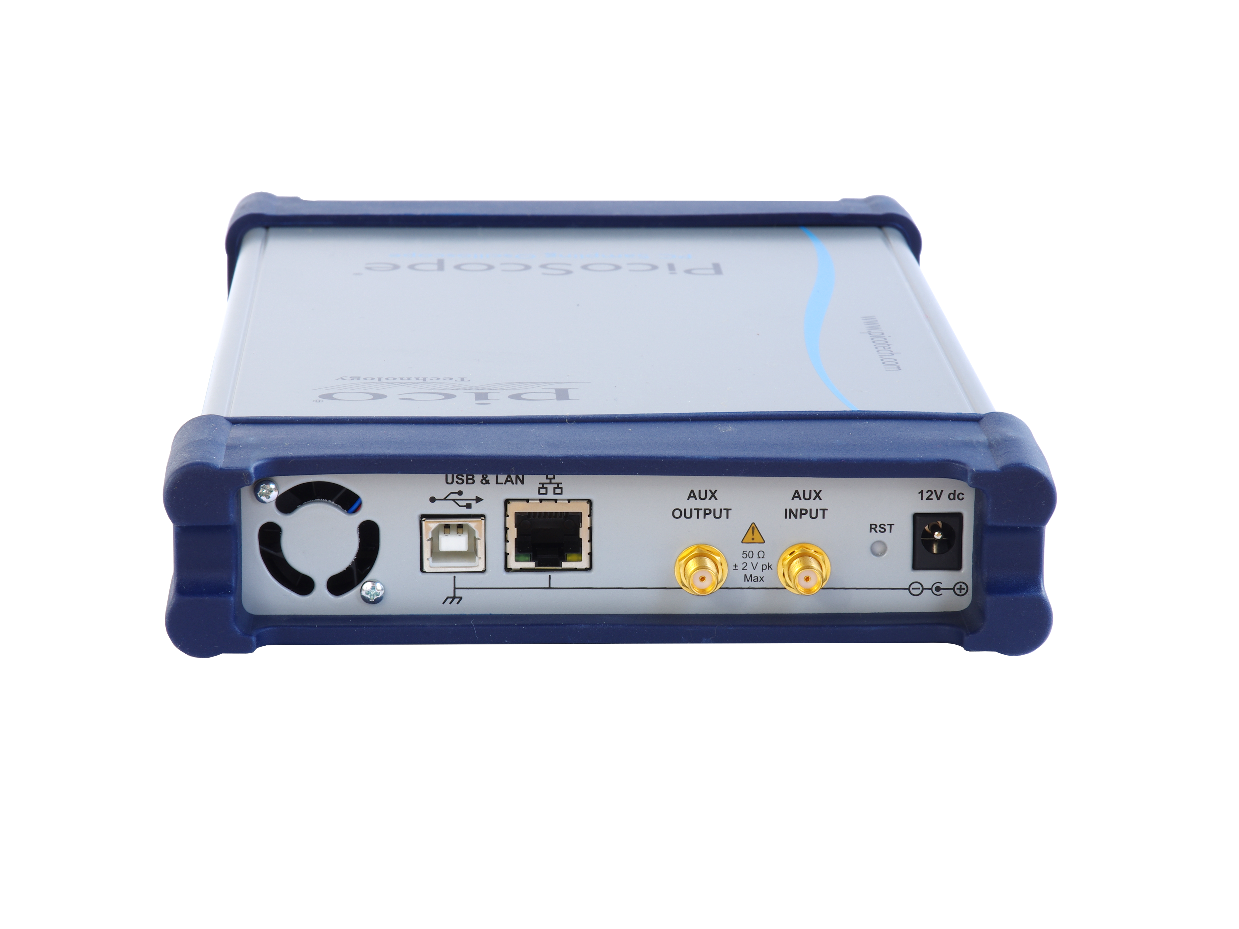
| PC connection |
USB 2.0 (compatible with USB 3.0) |
| LAN connection |
10/100 Mbit/s |
| PC requirements |
Microsoft Windows XP (SP2 or SP3), Vista, 7, 8 or 10.
32‑bit or 64‑bit versions. |
| Dimensions |
170 mm x 285 mm x 40 mm (W x D x H) |
| Weight |
1.3 kg max. |
| Compliance |
FCC (EMC), CE (EMC and LVD) |
| Warranty |
5 years |