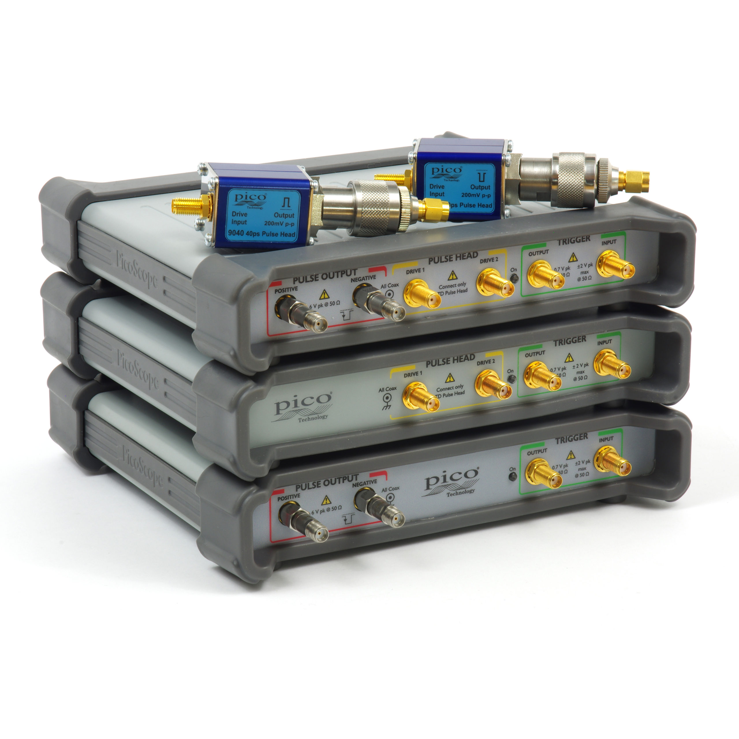
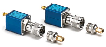
Differential picosecond pulse generators
PG911 and PG914
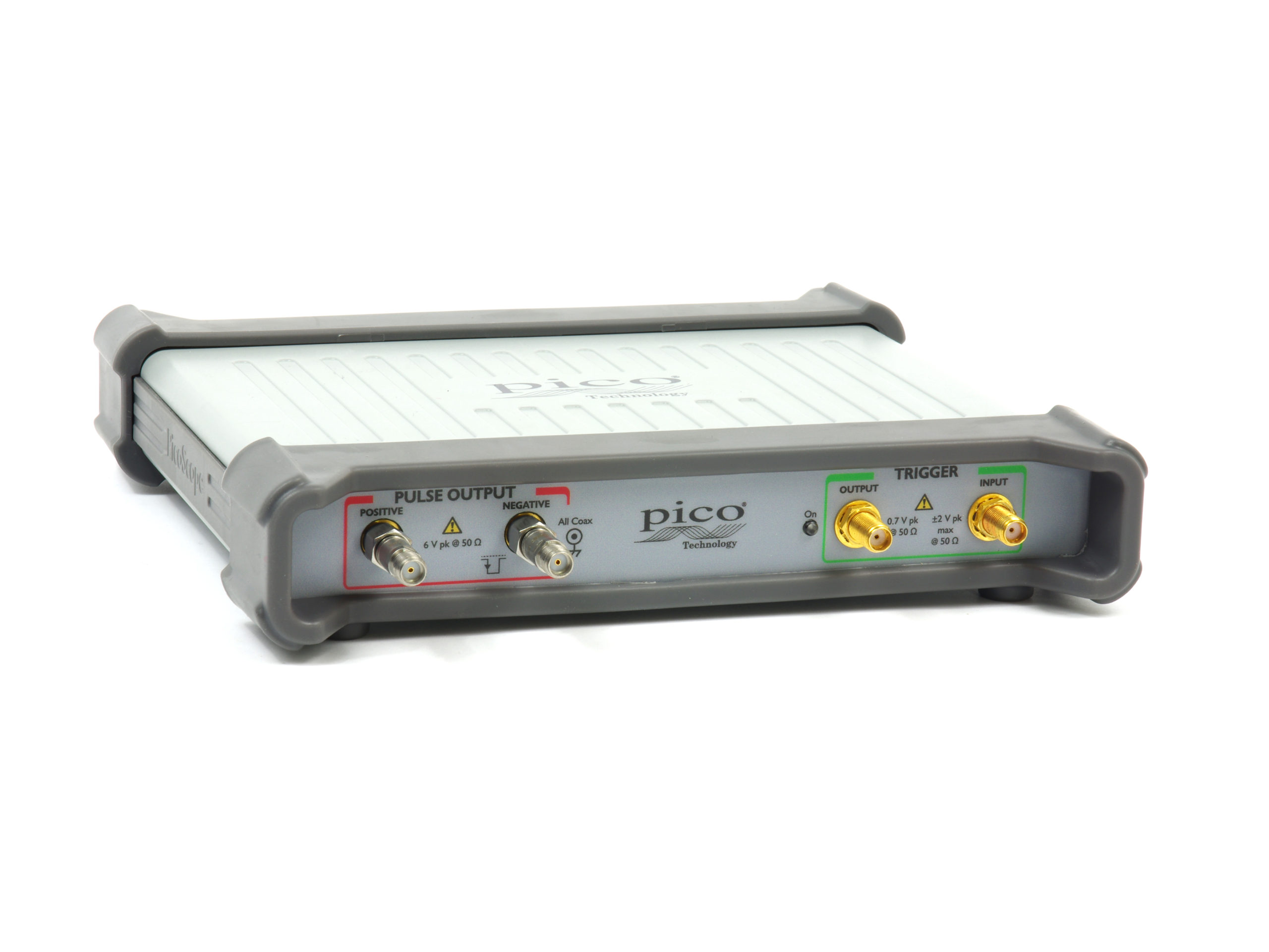
- Integral 50 Ω SMA(f) Step Recovery Diode outputs
- < 60 ps transition time
- Dual 2.5 to 6 V variable amplitude outputs
- ±1 ns in 1 ps steps timing deskew
- 200 ns to 4 μs pulse width
- 1 μs to 1 s internal clock period
- < 3 ps RMS jitter relative to external trigger
- –20 dB 10 GHz SMA(m-f) attenuator included with Step Recovery Diode outputs
|
 |
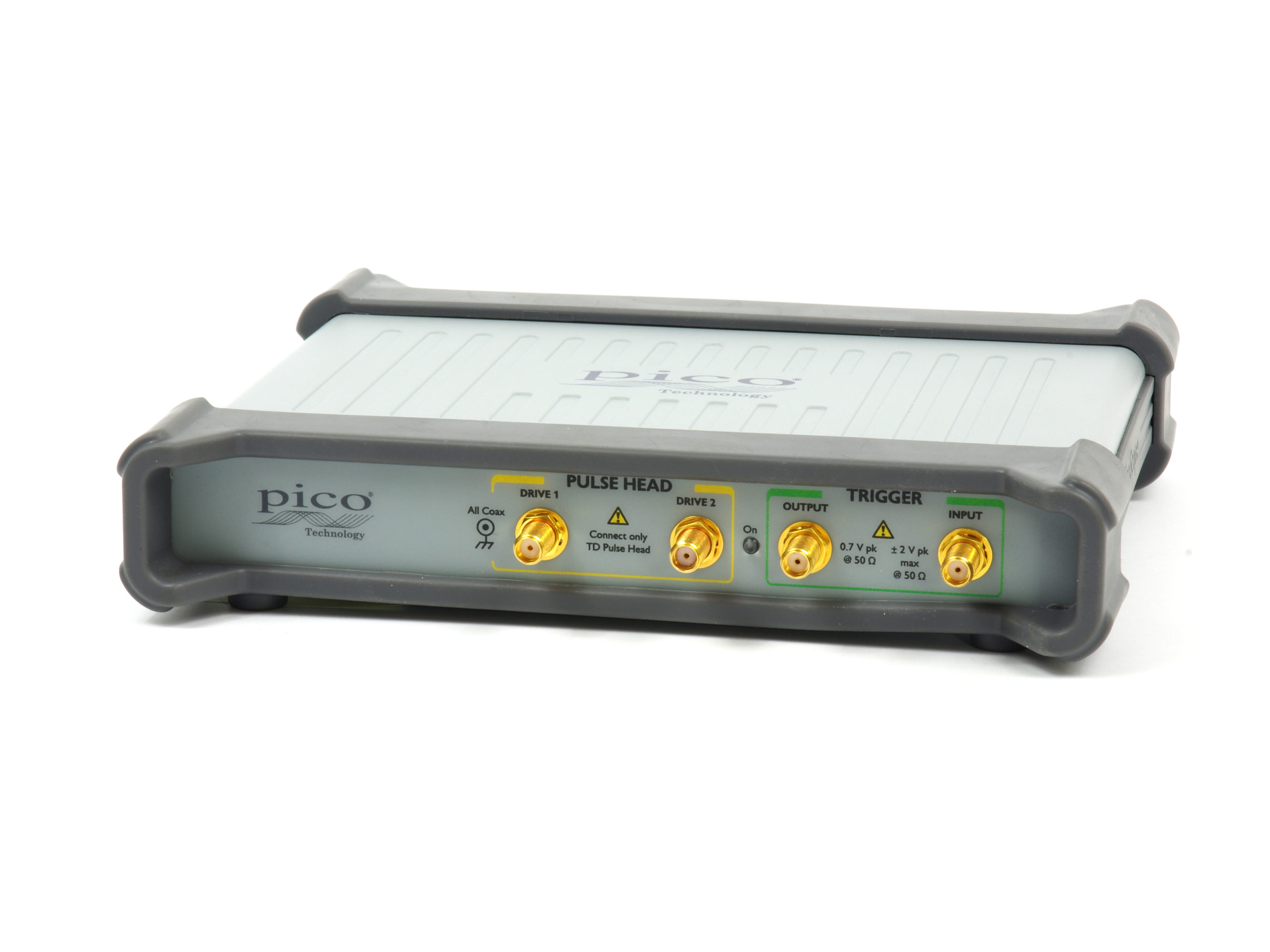
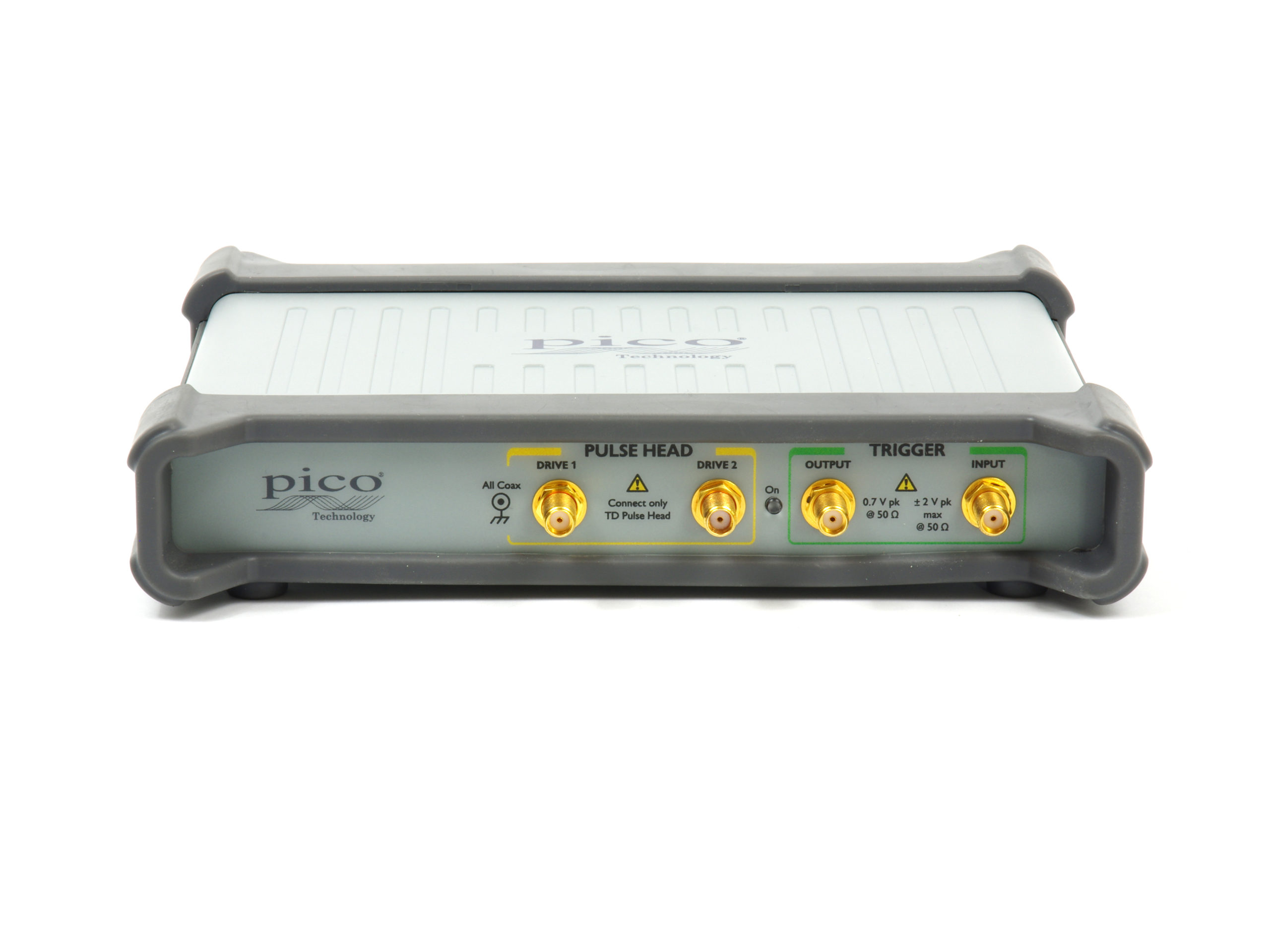
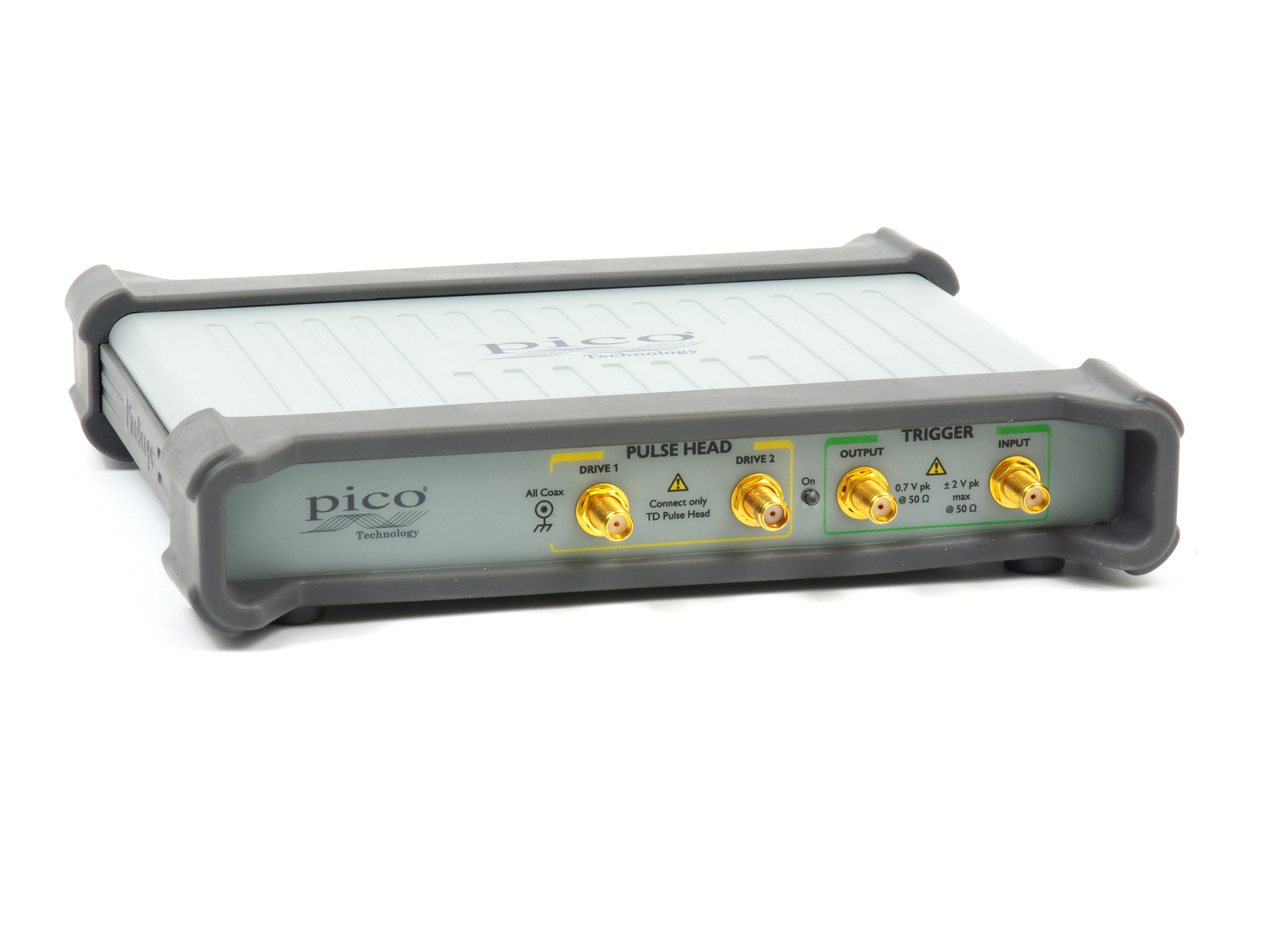
PG912 and PG914
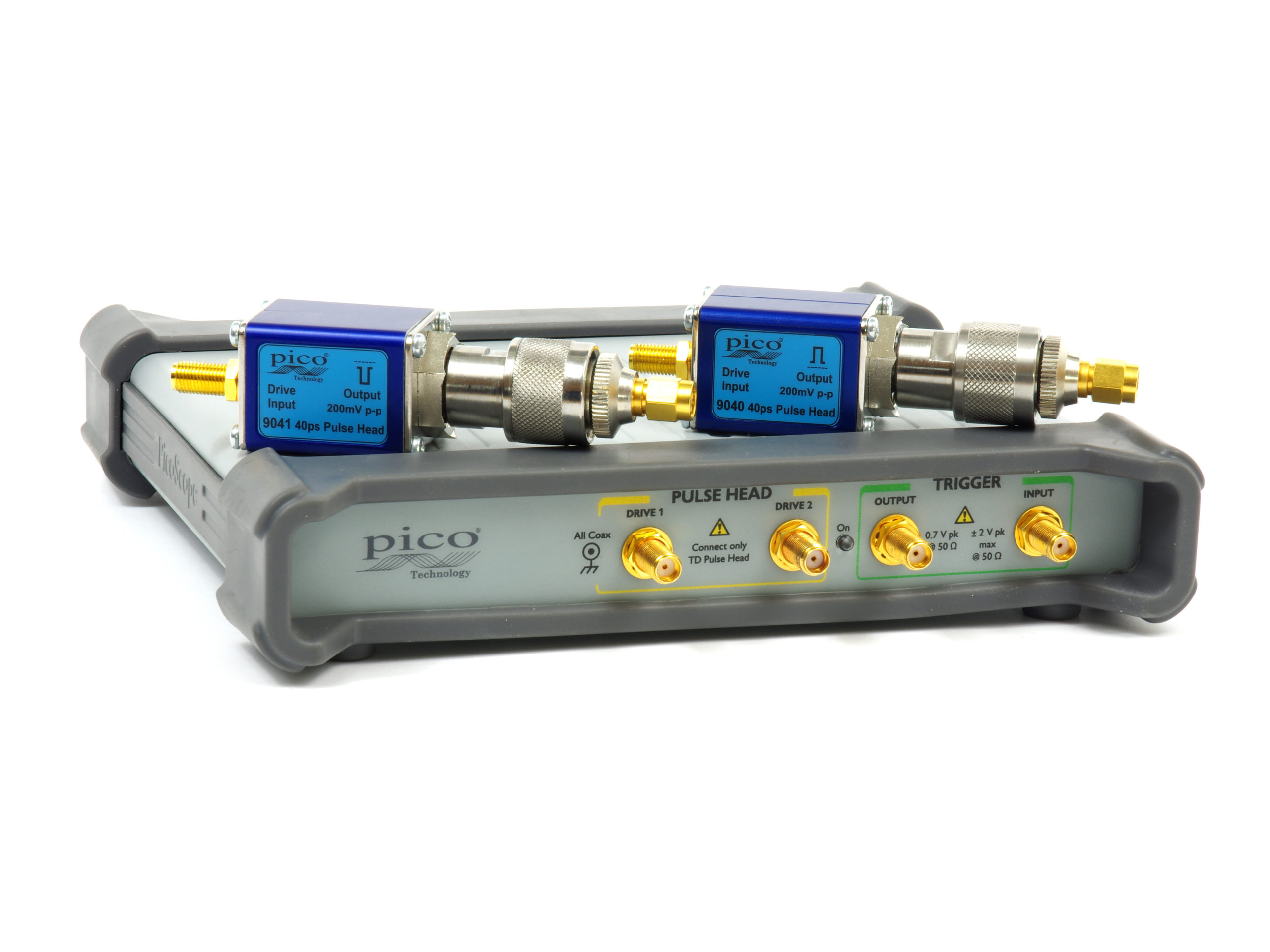
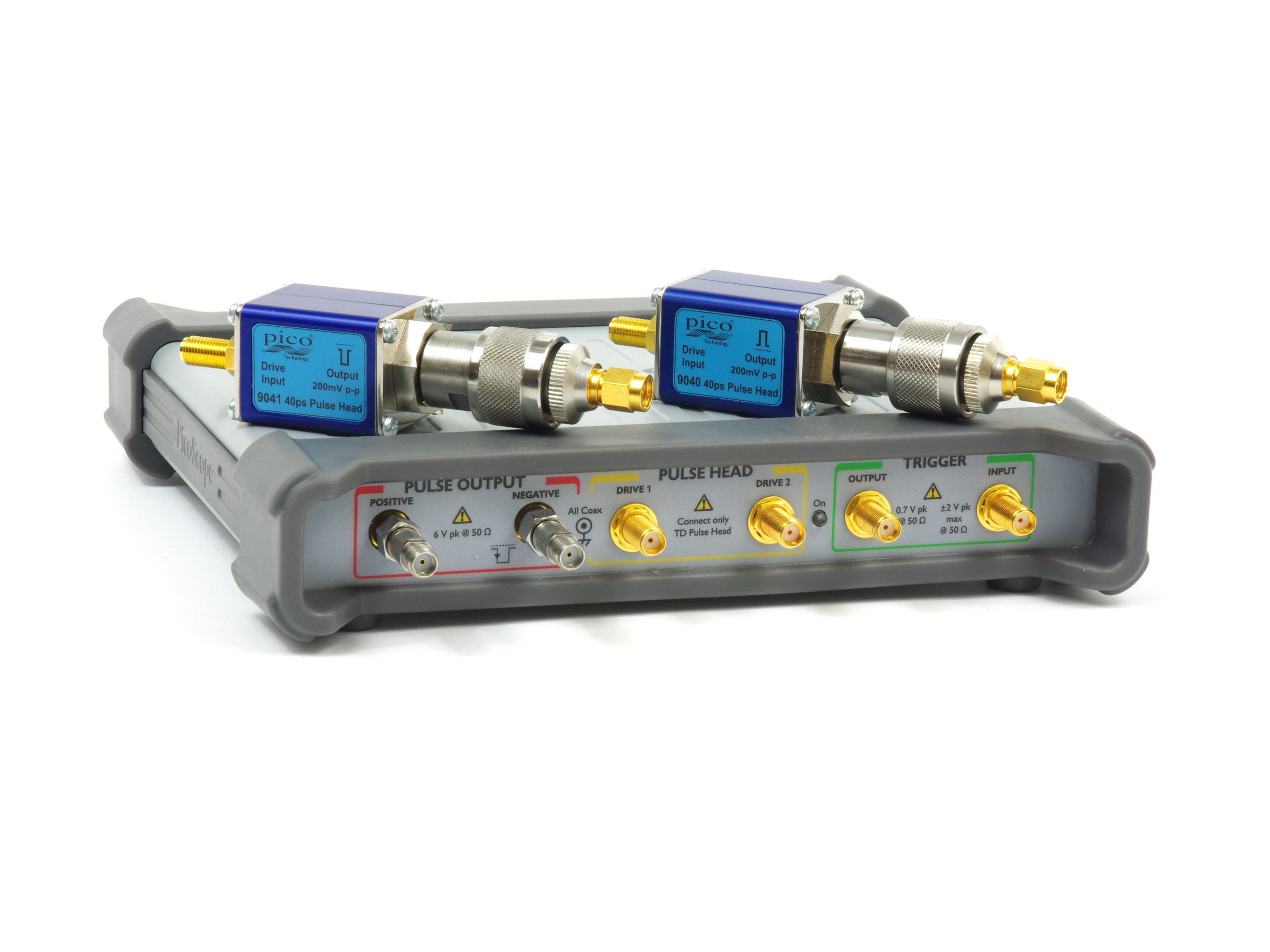
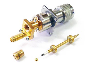
- External 50 Ω N(m) positive and negative Tunnel Diode pulse heads
- < 40 ps transition time
- Dual > 200 mV fixed amplitude outputs
- ±200 ps in 1 ps steps timing deskew
- Inter-series N(f) – SMA(m) adapter included with Tunnel Diode pulse heads
The fast-transition pulse can stimulate a transmission path, device or network with a broad spectrum signal in a single instant. Such a pulse is very useful for many of the high-speed broadband measurements that we need to make; for instance in time-domain reflectometry, semiconductor test, gigabit interconnect and port test and in radar.
Differential high-speed data in particular dominates the measurement challenge in our digital, computing, interconnect and telecommunications systems. Surprisingly, cost-effective fast-transition differential pulse generators have been very hard to find … until now!
Typical applications include:
- TDR/TDT network and match analysis
- Spectral and flatness measurements
- Timing, jitter and crosstalk determinations
The PicoSource PG900 Pulse Generators can partner the PicoScope 9300 20 GHz Sampling Oscilloscope in many of these applications.
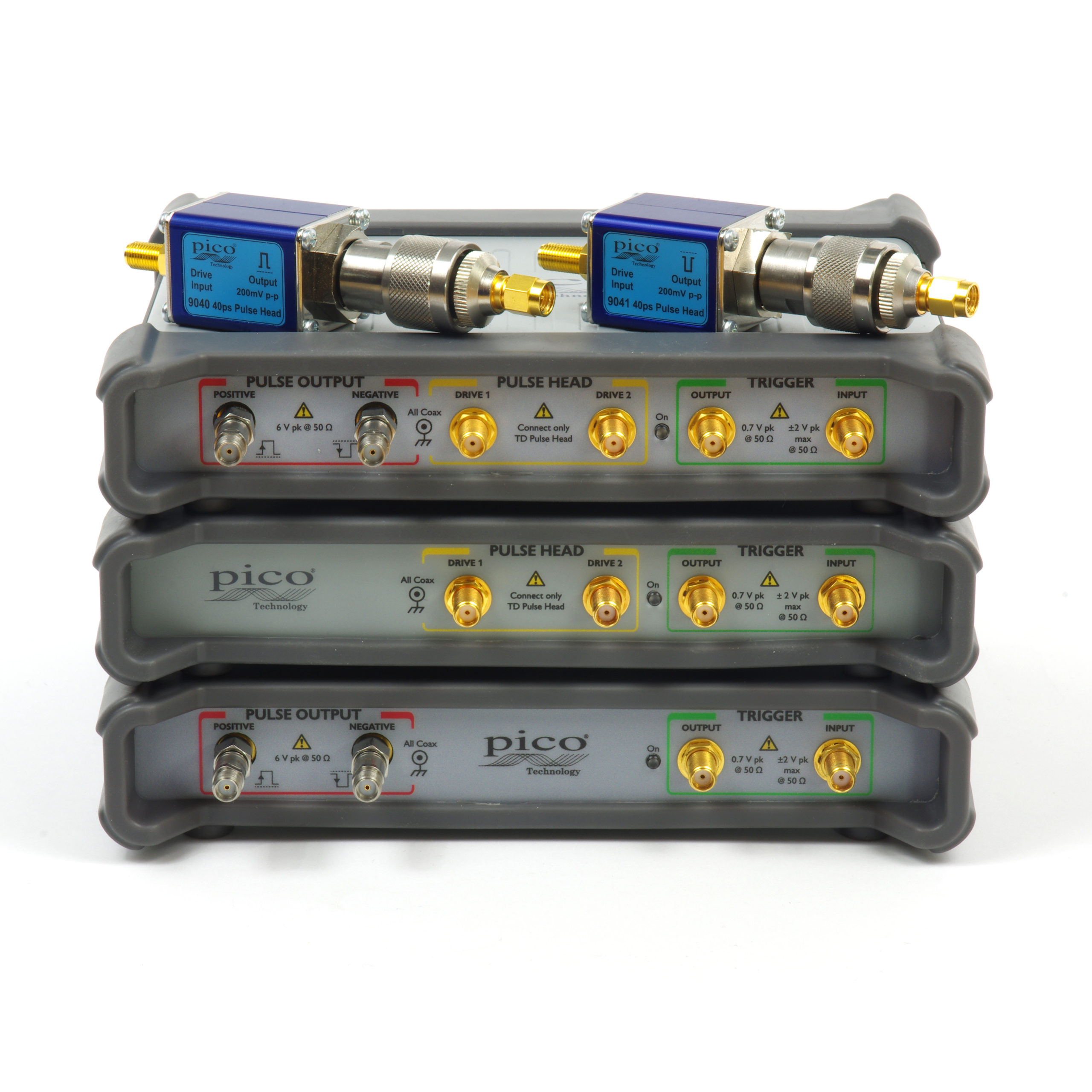
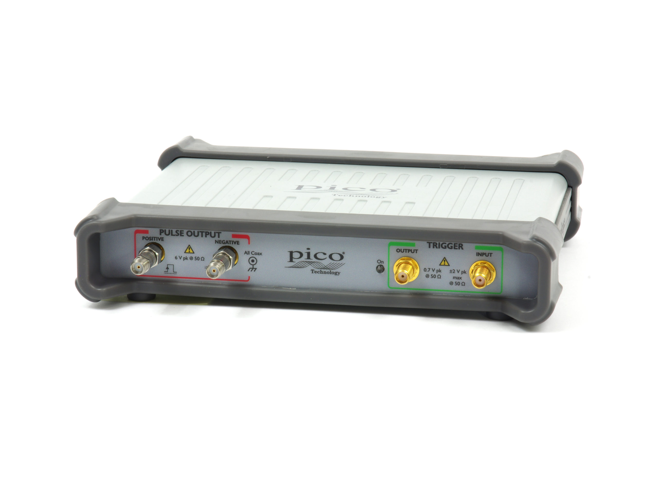
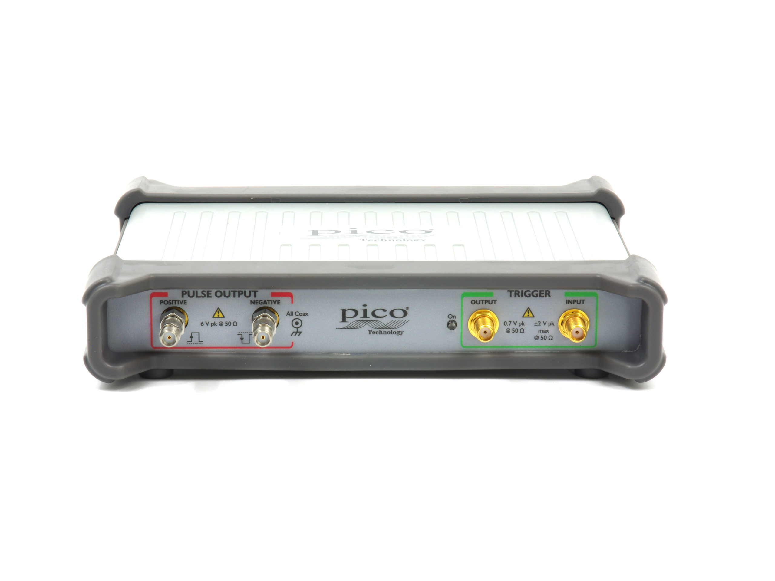
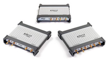
A versatile, portable triggered differential USB pulse generator
The PicoSource PG900 Series are low-jitter triggered differential USB pulse generators. Pulse outputs are optimized for broad spectral content (fastest transition time) to best suit spectral and time-domain transmission and reflectometry measurements. An internal clock is provided for stand-alone, self-triggered operation and trigger input and output allow the generators to source or respond to system triggers. Differential outputs ensure that the proliferation of gigabit differential interconnect and systems can all be addressed (e.g. SATA, USB3, HDMI, Ethernet).
Essential to any differential test or measurement is the ability to adjust for small but significant velocity and path length differences that are bound to exist in any measurement setup. The PG900 pulse outputs can each be adjusted (time-skewed) in 1 ps increments to deskew path differences before the measurement, or to deliberately stress a transmission path with timing skew.
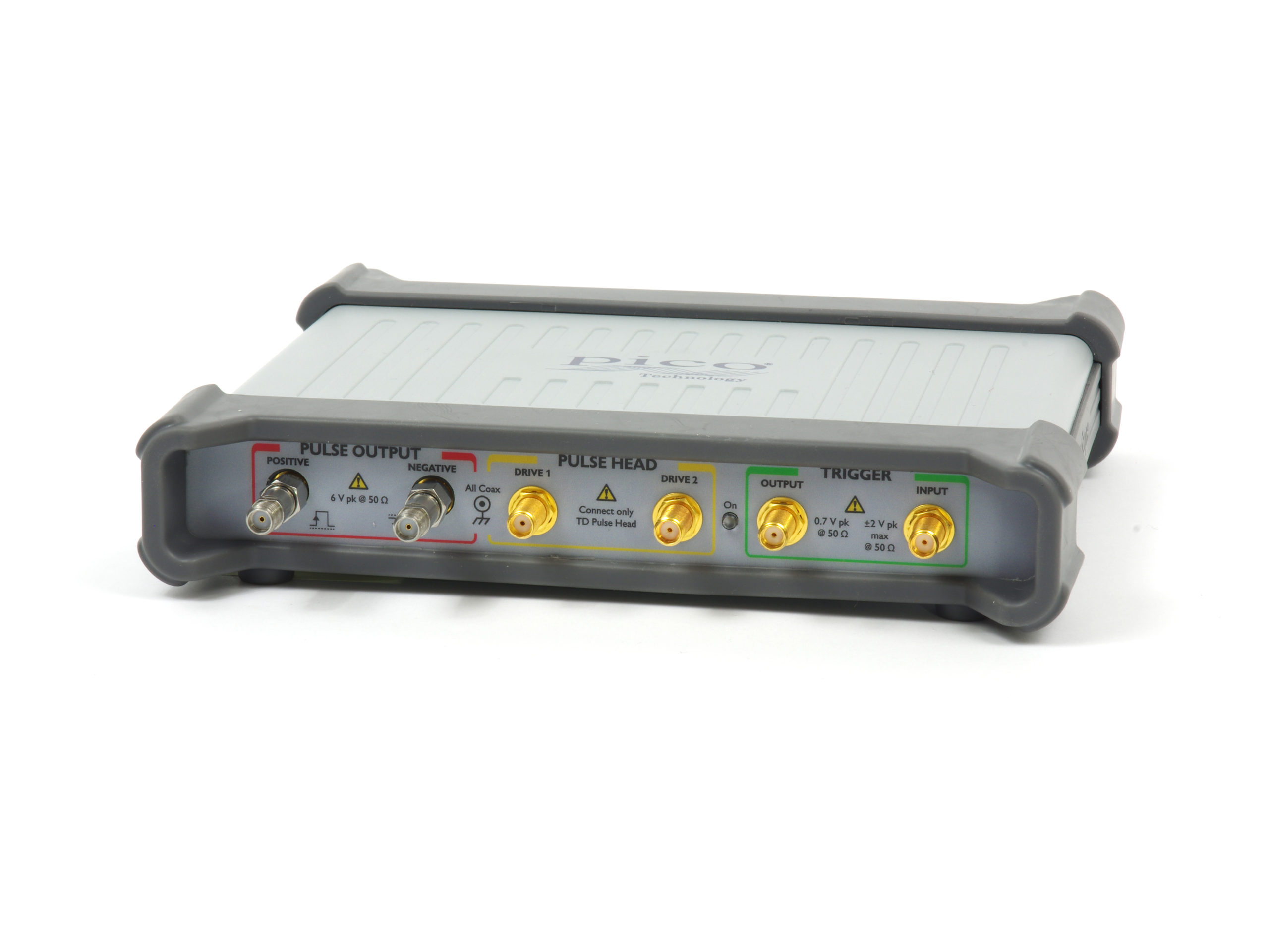
Despite their small size and portability the PicoSource PG900 generators pack quite a punch, with integrated Step Recovery Diode outputs of up to 6 V pk each into 50 Ω. That’s a whopping 12 V pk differential pulse amplitude to drive lossy paths or stress system ports. Outputs are adjustable in 10 mV steps down to 2.5 V pk. A user-settable amplitude limit is provided to protect more sensitive system ports and 20 dB attenuators are supplied fitted to the pulse outputs for small-signal and optimum-match applications.
Step Recovery variable amplitude pulse
The positive (fast rise) and negative (fast fall) pulses are both ground referenced and each pulses in opposite polarity to their user selected amplitude. This amplitude (the ‘mark’) is held for the user-selected pulse width and then returns to ground. Further pulses are prevented for the user set hold-off period and thereafter will repeat at 40 ns after the next received trigger. When the internal clock is selected, the pulse will repeat at the user-set period and holdoff is inactive. An output trigger is generated 40 ns before every pulse, however initiated.
Pulse transition time is typically 55 ps and spectral content (compared with a simulated ideal infinitely fast edge) extends to around 13 GHz @ –10 dB.
The negative (fast fall) pulse can be selected for even faster transition time by selecting ‘fast’ rather than ‘smooth’ mode. Pulse aberration is compromised but transition time is typically 45 ps and spectral content extends to around 14 GHz @ –10 dB.
Typical pulse shape as captured on a PicoScope 9300 20 GHz Sampling Oscilloscope are shown to the right.
Tunnel Diode Head fixed-amplitude pulse
The positive (fast rise) and negative (fast fall) pulses are both ground-referenced and each pulses in opposite polarity to its user-selected amplitude. This amplitude (the ‘mark’) is held for the user-selected pulse width and then returns to ground. Further pulses are prevented for the user-set holdoff period and thereafter will repeat at 40 ns after the next received trigger. When the internal clock is selected, the pulse will repeat at the user-set period and holdoff is inactive. An output trigger is generated 40 ns prior to every pulse, however initiated.
Pulse transition time is typically 55 ps and spectral content (compared with a simulated ideal infinitely fast edge) extends to around 13 GHz @ –10 dB.
The negative (fast fall) pulse can be selected for even faster transition time by selecting ‘fast’ rather than ‘smooth’ mode. Pulse aberration is compromised but transition time is typically 45 ps and spectral content extends to around 14 GHz @ –10 dB.
Typical pulse shape as captured on a PicoScope 9300 20 GHz Sampling Oscilloscope is shown to the right.
PicoSource PG900 Series applications
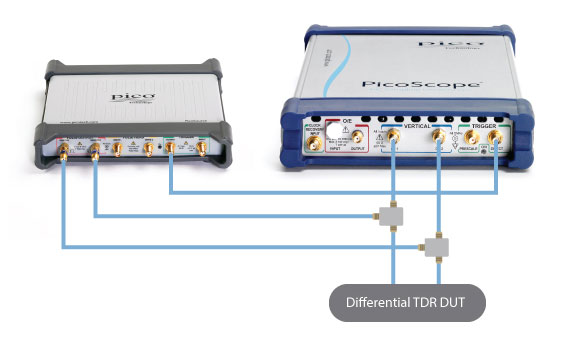
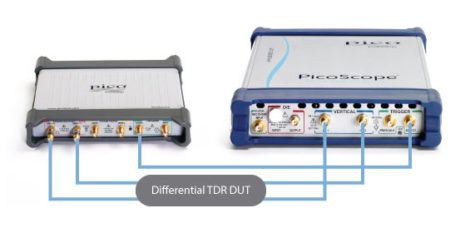
TDR applications with a PicoScope 9300 Sampling Oscilloscope
Controlled over USB from a single PC, the PG900 Pulse Generators can be used with a PicoScope 9300 Sampling Oscilloscope to realize time domain reflectometry with the models that do not integrate that functionality (PicoScope 9301, 9302, 9321 and 9341).
Single-ended measurements are possible using just one pulse source and an oscilloscope channel. |
 |
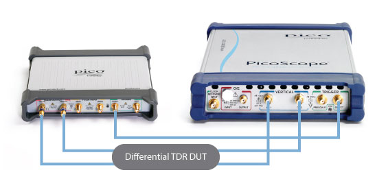
TDT applications with a PicoScope 9300 Sampling Oscilloscope
Controlled over USB from a single PC, the PG900 Pulse Generators can be used with a PicoScope 9300 Sampling Oscilloscope to measure time domain transmission with those models that do not include that function (PicoScope 9301, 9302, 9321 and 9341). They may also add the versatility of a remotely placed signal generator for long line or installed system testing with any of the PicoScope 9300 models.
Single-ended measurements are possible using just one pulse source and an oscilloscope channel. |
 |
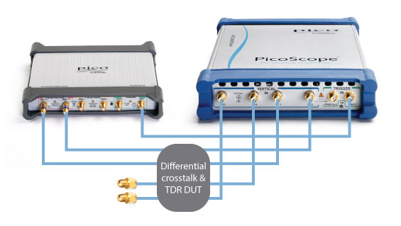
TDT and crosstalk with a PicoScope 9341 Sampling Oscilloscope
Controlled over USB from a single PC, the PG900 Pulse Generators can be used with a PicoScope 9341 Four-Channel Sampling Oscilloscope for simultaneous time domain transmission and crosstalk assessment.
Single-ended measurements are possible with a two-channel sampling oscilloscope. Differential measurements can also be tackled by first measuring transmission and then changing connections for crosstalk measurement. Unconnected ports should always be correctly terminated. |
 |
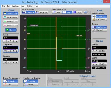
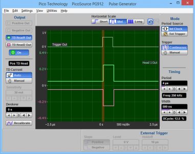
PicoSource PG900 software
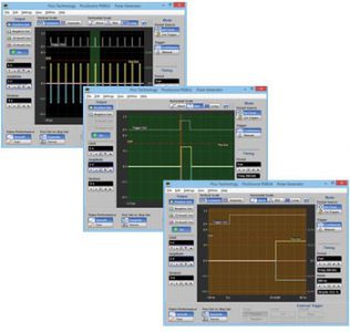
Pulse control PC software
The PicoSource PG900 Series generators are USB controlled from a Microsoft Windows PC running PicoSource PG900 software that is provided with the product. This is a very straightforward control application featuring a helpful graphical display of the pulse, limits and trigger settings as they are applied. Default and User pulse settings can be saved for future recall.
The pulse and trigger waveform displays can be toggled between three timebase settings to show the timing relationship of trigger and pulse, the pulse period or the pulse train being output. |
 |
Please give us your feedback about PicoSource PG900 Series
Your opinion is very important to us. We appreciate your feedback and will use it to evaluate changes and make improvements in our products:
PicoSource PG900 Series Downloads
Here you can download the latest PicoSource PG900 Series Data Sheets, Manuals, Guides and other relevant documents:
PicoSource PG900 Series specifications
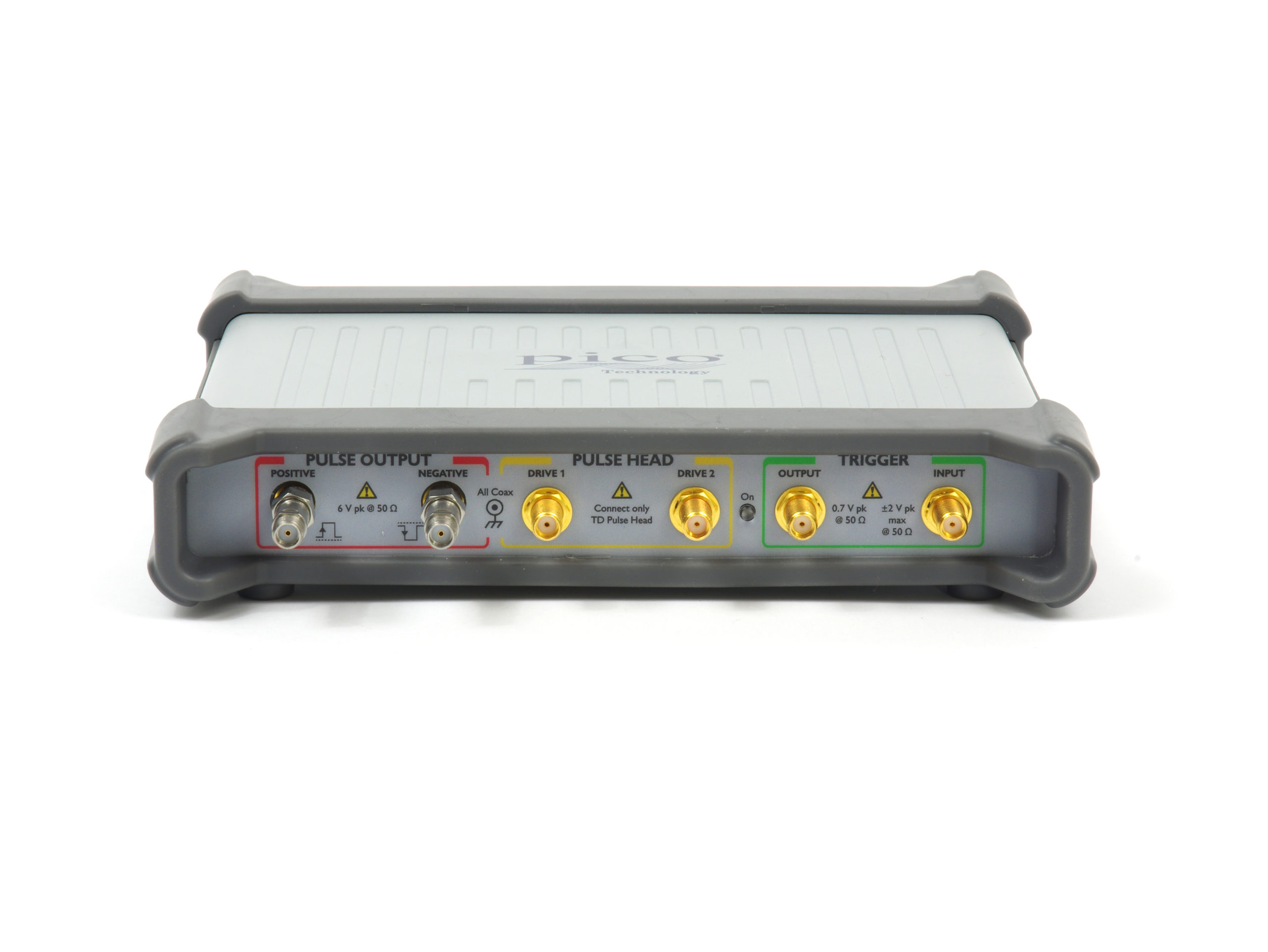
| Integrated step recovery diode pulse outputs |
| Pulse outputs |
Positive-going (fast rise) and negative-going (fast fall) outputs returning to 0 V.
Adjustable amplitude and timing parameters. Fast transition on leading edge. |
| Output impedance |
50 Ω |
| Output connector |
SMA(f) |
| Output amplitude |
Adjustable 2.5 V to 6 V in 10 mV steps |
| Output accuracy |
±10% |
| Output amplitude limit |
2.5 V to 6 V, adjustable in 100 mV increments |
| Duty cycle limit |
50% maximum (for 2.5 V to 4 V amplitude)
20% maximum (up to 6 V amplitude) |
| Differential deskew range |
Adjustable in 1 ps steps over 2 ns range |
|
Positive or negative-going, smooth mode: |
Negative-going, fast mode: |
| Pulse transition time |
< 60 ps (10% to 90%) (smooth mode) |
< 50 ps (10% to 90%) |
| Pulse aberrations |
< +20%, –10% for first 2 ns
< ±7% to 10 ns
< ±2% to pulse width –50 ns |
< (+40%, –10%) |
| Trailing edge transition time |
< 8 ns (10% to 90%) |
PicoSource PG912 and PG914
| Drive outputs with tunnel diode pulse heads |
| PS9040 Positive tunnel diode pulse head |
Positive-going (fast rise) output on < 70 mV pedestal.
Fixed amplitude and adjustable timing parameters.
Fast transition on leading edge. |
| PS9041 Negative tunnel diode pulse head |
Negative going (fast fall) output on < –70 mV pedestal.
Fixed amplitude and adjustable variable timing parameters.
Fast transition on leading edge. |
| Output impedance |
50 Ω, ±2 Ω |
| Output connector |
N(m) |
| Output amplitude |
Fixed 200 mV |
| Output accuracy |
±25% |
| Differential deskew range |
Adjustable in 1 ps steps over 200 ps minimum, 300 ps typical |
| Pulse transition time |
< 40 ps (10 % to 90%) |
| Pulse aberrations |
< ±20%, for first 2 ns
< ±7% to 15 ns
< ±2% to (pulse width – 50 ns) |
| Trailing edge transition time |
< 8 ns (10% to 90%) |
| Dimensions (each pulse head) |
80 mm x 28 mm x 25 mm |
| Weight (each pulse head) |
125 g |
All models and outputs
| Pulse timing |
| Pulse trigger source |
External input, manual single shot event or internal clock |
| Jitter relative to leading edge |
3.0 ps RMS typical. 3.5 ps RMS maximum. |
| Post-trigger delay to pulse leading edge |
Fixed 42 ns ±2 ns
Allows leading-edge capture on sampling oscilloscopes |
| Pulse width and accuracy |
200 ns to 4 µs ± 10% ± 50 ns, user adjustable in steps of 25 ns |
| Pulse width jitter |
< 150 ppm of width RMS |
| External trigger hold-off |
Adjustable 1 μs to 1.3 ms in steps of 200 ns, to maximum of 345 ms in steps of < 15 ppm |
| Internal clock specification |
| Period and accuracy |
Adjustable 1 µs to 1 s, ±100 ppm ±10 ns in steps of 200 ns |
| External trigger input specification |
| Impedance |
50 Ω ±1% |
| Connector |
SMA(f) |
| Maximum input level |
+16 dBm, or ±2 V DC or AC pk |
| Bandwidth |
1 GHz, DC coupled |
| Trigger polarity |
Selectable rising or falling edge |
| Trigger level |
Selectable –1 V to +1 V in steps of 1 mV |
| Sensitivity |
< 50 mV pk-pk DC to 100 MHz, rising linearly to 100 mV pk-pk at 1 GHz |
| Minimum pulse width |
500 ps at 100 mV pk-pk |
| External trigger output specification |
| Trigger output pulse |
Fixed amplitude and timing parameters, positive edge polarity, trigger is leading edge |
| Impedance |
50 Ω, ±0.5 Ω |
| Connector |
SMA(f) |
| Amplitude and offset |
> 700 mV fixed, on logic low of 0 V ± < 100 mV |
| Pulse width |
500 ns, ±100 ns |
| Trigger to trigger output delay |
4 ns, ±1 ns |
| Trigger to trigger output jitter |
2.5 ps rms typical. 3 ps rms maximum. |
| Transition time |
< 400 ps (10% to 90%) |
| General specifications |
| AC to DC adaptor |
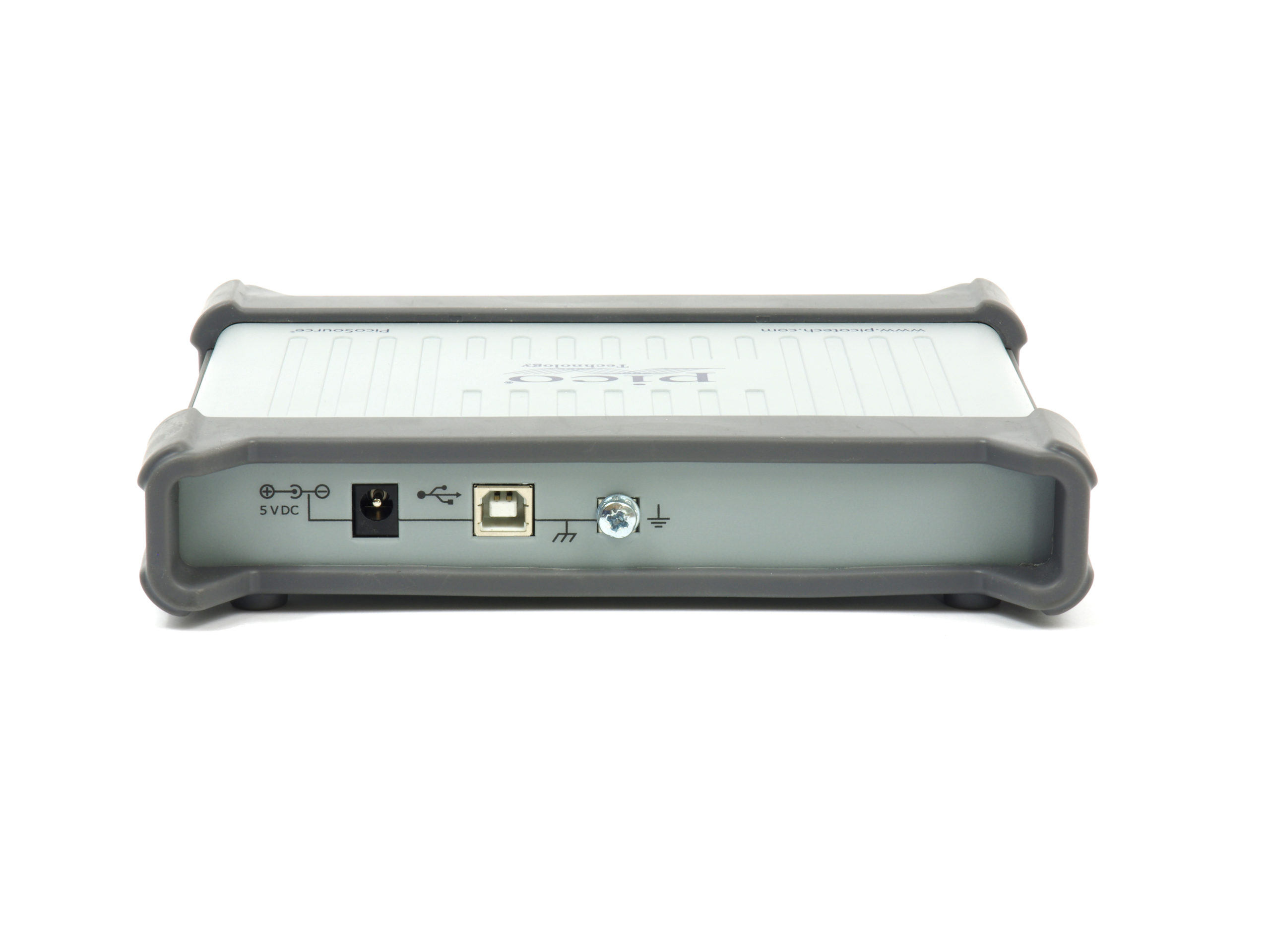
5 V ±5% at 1.6 A, 8 W, universal plug (adaptor included) |
| PC connection |
USB 2.0 (USB 1.1 and USB 3.0 compatible), 1.8 m USB 2.0 lead included |
| PC requirements |
Windows XP SP3 to Windows 8 |
| Operating temperature range |
+5 °C to +35 °C |
| Storage temperature range |
–20 °C to +50 °C |
| Temperature range for stated specifications |
+15 °C to +25 °C or TCAL (temperature of calibration) ±5 °C |
| Operating humidity range |
< 85% RH (non-condensing) at +25 °C |
| Storage humidity range |
< 95% RH (non-condensing) |
| Dimensions (instrument) |
190 mm W x 180 mm D x 40 mm H |
| Weight (instrument) |
560 g |
| Warranty |
5 years |
Specifications describe guaranteed performance over the stated temperature range and apply after the instrument’s temperature has been stabilized in 1 hour of continuous operation. All specifications are subject to change without notice.
Factory calibration cycle. For optimum performance, the instrument should have a complete verification of specifications once every 12 months.