
Features and Applications
Features and Benefit
- DC to 30, 20 or 12 GHz Bandwidth
- 2 Channels
- 1.6 % Vertical Gain Accuracy
- 14-Bit Vertical Resolution
- Dual Time Base 10 ps/div to 2 ms/div
- 100 fs Sampling Interval
- DC to 1 GHz Full-function Direct Trigger
- 12 GHz Prescaled Trigger
- Up to 2.7 Gbps Clock Recovery Trigger
- 40 ps TDR/TDT
- Up to 4 k-point record length per channel
- Normal, Infinitive, Variable Persistence and Color Graded Display Modes
- High Resolution Cursor and Automatic Waveform Measurements with Statistics
- Waveform Processing including FFT
- Statistical analysis with Time and Voltage Histograms
- Automated Eye-Diagram Measurements for NRZ and RZ signal types
- Automated Mask test with Predefine Standard, and Custom Masks
- Familiar Windows Intuitive Graphical User Interface
- Built-in information system
- USB 2.0 (FS) or IEEE1284 (ECP mode) UDS-2000 to PC Interface
- Win95/98/ME/NT4/2000/XP Compatibility
Applications
- 20 GHz or 12 GHz Electrical Bandwidth
- 8 GHz or 3 GHz Unfiltered Optical Bandwidth
- Two electrical /One optical channel
- Three Bessel-Thomson filters
- 750 nm to 1650 nm Wavelength range
- DC to 1 GHz Full-function Trigger
- 12-GHz Optional Prescaled Trigger
- Optional Clock Recovery Trigger
Product Description
The UDS-2000 is the world Faster Series PC-Sampling Oscilloscopes, which offers the widest range of measurements and waveform processing capabilities of any multi-Gigahertz PC-scope. With excellent measurement repeatability, exceptional vertical resolution and fast display update rate, the UDS-2000 is a powerful measurement tools for semiconductor testing, TDR characterization of circuit boards, IC packages and cables, and high-speed digital data communications. It is a key tool for R&D and production testing.
UDS-2000 instruments are PC-Sampling Oscilloscopes, or oscilloscopes for Personal Computer. They require just USB 2.0 (FS) or IEEE1284 (ECP mode) connector in your PC to give you the computing power of a stand-alone instrument within your PC.
All models of the UDS-2000 series use sequential equivalent-time sampling technology to achieve bandwidth of up to 30, 20 or 12 GHz. Data acquisition and measurement analysis are performed in parallel, enabling the instrument to achieve outstanding measurement throughput. The instruments provide fast acquisition, repeatable waveform performance analysis with automated direct or statistical measurements, Markers and Histograms, Math or FFT analysis, high-resolution TDR/TDT, Color-Graded Display, Parametric Limit Testing, and Mask Template Testing. These measurements can be used independently or in concert.
The GHz-bandwidth and the low-noise specifications allow very precise measurements on low-level, high-speed signals. Time base stability, accuracy, and resolution allow characterization of jitter in the most demanding applications. The instrument provides you with necessary capabilities to test and measure analogue and digital circuits.
The UDS-2000 oscilloscopes are powerful and versatile instruments for waveform analysis in research, development, production, and evaluation testing throughout the telecommunications and data communications industries. The instrument has been designed to give you the highest accuracy, measurement speed, and ease-of-use for characterizing high-speed digital communications waveforms. TDR/TDT is available for optimization of circuit board and transmission lines. Data acquisition and measurement analysis is performed in parallel with PC, enabling oscilloscope to achieve outstanding measurement throughput. The UDS-2000 provides fast, repeatable communications waveform performance analysis with automated pulse and eye-diagram statistical measurements. Electrical conformance tests to define and industry standard eye-diagram masks or pulse templates are easily executed.
Digital Communications Analysis
The UDS-2000 Oscilloscopes designed for communications applications. They provide solutions for design and evaluation of datacomm/telecomm components, transceiver subassemblies, and transmission systems. The UDS-2000 generates measurement results, not just raw data, with time and voltage histograms, mask testing, and statistical pulse parameter measurements. It provides a communications-tailored measurement set that includes jitter, noise, duty cycle, overshoot, undershoot, extinction ratio and amplitude measurements. With the addition of the UDX-R01/R02/R03 Clock Recovery Heads, reliable parametric testing up to 2.7 Gbps bit rates becomes easy even when you do not have access to a clock signal trigger.
TDR and TDT
TDR measurements are focused on high-speed applications where it is necessary to optimize electrical system components, such as microstrip lines, PC board traces, N-edge launchers and coaxial cables where imperfections cause signal distortion and reflections. Signal integrity is a critical requirement in high-speed digital signal transmission.
Familiar Windows-95/98/ME/NT4/2000/XP User Interface
The UDS-2000 Oscilloscopes have a Windows intuitive graphical user interface, so you won’t have to spend a lot of time learning or relearning the instrument. Pull-down menus give you easy access to advanced features and icons provide quick access to an extensive set of common tests and measurements.
Built-in Information System
The UDS-2000 Oscilloscopes have a built-in information system that puts measurement assistance at your fingertips. You’ll no longer have to look for the manual when you need help setting up the oscilloscope or making complex measurements. A measurement set-up guide gives you step-by-step instructions for many measurements and procedures. Links on the measurement screen take you directly to the information you need in the on-line manual.
Specifications and Characteristics
|
Channel (Vertical) Number of Channels 2 (Simultaneous acquisition) |
||||||||||||||||||||||||
|---|---|---|---|---|---|---|---|---|---|---|---|---|---|---|---|---|---|---|---|---|---|---|---|---|
|
||||||||||||||||||||||||
|
Scale Factors (Sensitivity) 1 mV/div to 255 mV/div (Full scale is 8 divisions). Adjustable from 1 mV/div to 255 mV/div in a 1-2-5-10 sequence. Also adjustable in fine increments 0.5 mV to 2 mV |
||||||||||||||||||||||||
|
DC Difference Voltage Accuracy ± 1.6 % of full vertical scale ± 2 mV |
||||||||||||||||||||||||
|
DC Offset Range Adjustable from -1 V to 1 V in a 25 mV increments (coarse). Also adjustable in fine increment 1 mV. |
||||||||||||||||||||||||
|
ADC 14-Bits. |
||||||||||||||||||||||||
|
Vertical Resolution 125 uV/LSB without averaging. Up to 16 bit with averaging. |
||||||||||||||||||||||||
|
Maximum operating input voltage 1.0 V p-p at ± 1 V range. |
||||||||||||||||||||||||
|
Maximum Safe Input Voltage 16 dBm, or ± 2 V (dc + peak ac). |
||||||||||||||||||||||||
|
Nominal Input Impedance (50 ± 1) OHm. |
||||||||||||||||||||||||
|
Input Connectors UDS-2030: K-type; UDS-2020 and UDS-2012: N-type (f). |
||||||||||||||||||||||||
|
Deskew (The difference in delay between channels) Can be nulled out with 1-ps resolution to compensate for differences in input cables or probe length. Up to 100 ns of skew can be nulled out. |
||||||||||||||||||||||||
|
Attenuation Attenuation factors may be entered to scale the oscilloscope for external attenuators connected to the channel inputs. Range: 0.00001:1 to 1,000,000:1. Units: Ratio or dB. Scale: Volt, Watt, Ampere, or Unknown. |
||||||||||||||||||||||||
|
Channel-to-channel isolation > 40 dB. |
||||||||||||||||||||||||
|
Time Base (Horizontal) Time Bases Main, Intensified, two Delayed, Dual Delayed. |
||||||||||||||||||||||||
|
Scale Factors Main Time Base: 10 ps/div to 2 ms/div (Full scale is 10 divisions). Delayed Time Bases: 10 ps/div to current Main Time Base setting. Adjustable in a 1-2-5-10 sequence. Also adjustable in fine increment 1 ps, or 0.1% and better. |
||||||||||||||||||||||||
|
Delta Time Interval Accuracy ± 0.4% of reading ± 15 ps ± 100 ppm of delay setting (maximum); ± 0.4% of reading ± 10 ps ± 100 ppm of delay setting (typical). |
||||||||||||||||||||||||
|
Note: Measured at a temperature within ± 3°C of horizontal calibration temperature. |
||||||||||||||||||||||||
|
Typical Timing Accuracy The time base uses a series of 2-ns blocks. Time base linearity and small discontinuities across these blocks contribute to the 10-ps accuracy specification. |
||||||||||||||||||||||||
|
Variable Delay (Time offset relative to trigger) Up to 1000 screen diameters of Delayed Time Base or 19.98 ms, whichever is smaller. |
||||||||||||||||||||||||
|
Minimum Delay (Minimum time offset relative to trigger) ‹ 40 ns. |
||||||||||||||||||||||||
|
Display Units Time or Bit Period. |
||||||||||||||||||||||||
|
Time Interval Resolution Screen diameter / (record length) or 100 fs, whichever is larger. |
||||||||||||||||||||||||
|
Trigger Trigger Sources External (Direct Trigger), External HF with different trigger heads, Internal Clock trigger (internally connected to direct trigger). |
||||||||||||||||||||||||
|
Trigger Holdoff Adjustable from 10 us to 30.72 ms in a 1-2-5-10 sequence, or in 2 ns increments. |
||||||||||||||||||||||||
|
Internal Clock Repetition Rate 10 us to 2 ms in a 1-2-5-10 sequence, or in 125 ns increments. |
||||||||||||||||||||||||
|
Direct Trigger Trigger Modes Triggered: causes the scope to trigger synchronously to the trigger input signal. Freerun: causes the scope to generate its own triggers. |
||||||||||||||||||||||||
|
Slope Positive: triggers on positive-slewing edge. Negative: triggers on negative-slewing edge. |
||||||||||||||||||||||||
|
Trigger Bandwidth and Sensitivity 100 mV p-p DC to 100 MHz. Increasing linearly from 100 mV p-p at 100 MHz to 400 mV p-p at 1 GHz. Pulse Width: 500 ps @ 400 mV p-p |
||||||||||||||||||||||||
|
RMS Jitter 2.5 ps + 50 ppm of delay setting (maximum); 2.0 ps + 30 ppm of delay setting (typical). |
||||||||||||||||||||||||
|
Note: Measured at 1 GHz with the triggering level adjusted for optimum trigger. |
||||||||||||||||||||||||
|
Trigger Level Range -1 V to 1 V. |
||||||||||||||||||||||||
|
Trigger Level Resolution 1 mV. |
||||||||||||||||||||||||
|
Trigger Hysteresis Normal: the trigger hysteresis is set so the instrument meets the trigger sensitivity specification. High Sensitivity: hysteresis is turned off to allow a best sensitivity to high-frequency signals. This mode should not be used for noisy lower frequency signals that may miss-trigger without hysteresis. |
||||||||||||||||||||||||
|
Maximum Safe Trigger Input Voltage ± 2 V (dc+peak ac) or 16 dBm. |
||||||||||||||||||||||||
|
Nominal Input Impedance (50 ± 1) OHm. |
||||||||||||||||||||||||
|
Trigger Coupling DC coupled. |
||||||||||||||||||||||||
|
Trigger Input Connector UDS-2030: SMA (f); UDS-2020 and UDS-2012: BNC (f) |
||||||||||||||||||||||||
|
External HF Trigger Several trigger heads enhance trigger possibilities of the UDS-2000 sampling oscilloscopes. See Compatible with the Oscilloscopes for details |
||||||||||||||||||||||||
|
UDX-T01 SMA (f) |
||||||||||||||||||||||||
|
UDX-P01 Prescaled trigger up to 12 GHz |
||||||||||||||||||||||||
|
UDX-P02 Prescaled trigger up to 18 GHz |
||||||||||||||||||||||||
|
UDX-P03 Low-Jitter Trigger less than 300 fs up to 12 GHz |
||||||||||||||||||||||||
|
UDX-R01 Clock recovery trigger for fixed 622 Mbps data rate |
||||||||||||||||||||||||
|
UDX-R02 Clock recovery trigger for fixed 2.488 Gbps data rate |
||||||||||||||||||||||||
|
UDX-R03 Clock recovery trigger 10 Mbps to 2.7 Gbps continuous data rate |
||||||||||||||||||||||||
|
Acquisition Number of Acquisition Channels 2 (Simultaneous acquisition). |
||||||||||||||||||||||||
|
ADC Resolution 14 -Bits. |
||||||||||||||||||||||||
|
Digitizing Rate DC to 100 kHz. The signal is sampled and digitized at a rate dictated by the trigger repetition rate and the time base range. If data acquisition is not trigger rate limited, the maximum sample rate is 100 kHz. |
||||||||||||||||||||||||
|
Acquisition Modes Sample (normal), Average, Envelope, or Peak Detect. |
||||||||||||||||||||||||
|
Average Modes Stable, Multiple, or Median. |
||||||||||||||||||||||||
|
Number of averages From 2 to 4096 in x2 sequence. |
||||||||||||||||||||||||
|
Envelope Modes Min, Max or both Min-Max values acquired over one or more acquisitions. |
||||||||||||||||||||||||
|
Peak Detect Mode High frequency and short repetitive glitch capture. Captures glitches of 20 ps using acquisition hardware at al horizontal scales. |
||||||||||||||||||||||||
|
Data Record Length 32 to 4096 points maximum per channel in x2 sequence. |
||||||||||||||||||||||||
|
Display Display Resolution Full: 640 points horizontally x 480 points vertically, Data: 501 points horizontally x 257 points vertically. |
||||||||||||||||||||||||
|
Display Style Dots; Vectors; Variable Persistence: time that each data point is retained on the display, persistence time can be varied from 100 ms to 20 s; Infinite Persistence; Variable Gray Scaling: five color levels that are used are one color that is varied in saturation and luminosity levels (in other words, different shades of the same color), refresh time an be varied from 1 s to 100 s; Infinite Gray Scaling; Variable Color Grading: with Color Grading selected, historical timing information is represented by temperature or spectral color scheme providing "z-axis" information about rapidly changing waveforms. Refresh time can be varied from 1 to 200 s, Infinite Color Grading. |
||||||||||||||||||||||||
|
Graticule Full Grid, Axes with tic marks, Frame with tic marks, Off (no graticule). |
||||||||||||||||||||||||
|
Screen Single: all waveforms are superimposed and are eight divisions high. Dual: with two graticules all waveforms can be displayed separately or are superimposed with four divisions high. Quad: with four graticules all waveforms can be displayed separately or are superimposed with two divisions high. When you selected dual or quad screen display every waveform channels, memories, and functions can be placed on specified graticule. |
||||||||||||||||||||||||
|
Display Format YT, XY or both YT & XY. |
||||||||||||||||||||||||
|
Colors You may choose a Default Color selection, or select your own Set Color. Different colors are used for display selected Item: background, channels, functions, waveform memories, FFTs, TDR/TDTs, and histograms. |
||||||||||||||||||||||||
|
Save/Recall Management Store and recall setups, waveforms, data base and screen images to both the hard drive and the floppy drive of the PC. Storage capacity is limited only by disk space. |
||||||||||||||||||||||||
|
File extensions for waveform files The following file extensions for waveform and setup files are used: Waveforms - .wfm for binary format, .txt for text format, .wfm, and .txt for both formats. Data base files - .cgs. Setup files - .set. |
||||||||||||||||||||||||
|
Operating System Microsoft Windows® 95/98/ME/NT4/2000/XP. |
||||||||||||||||||||||||
|
Waveform Save/Recall Up to four waveforms may be stored into Waveform Memories (M1-M4), and then recalled on display. |
||||||||||||||||||||||||
|
Save/Recall to Disk You can save or recall your acquired waveforms or data base to or from hard disk or floppy disk of PC. To save a waveform, use the traditional Windows "Save as"dialog box. From this dialog box you can create subdirectories, new waveform files, or overwrite existing waveform files. You can load file with a waveform or data base you have previously saved, into one of Waveform Memories, and then recall it on display. |
||||||||||||||||||||||||
|
Save/Recall Setups The instrument may store into the memory and then recall complete setups. |
||||||||||||||||||||||||
|
Autoscale Pressing the Autoscale key automatically adjusts the vertical of channels, the horizontal scale factors, and the trigger level for a display appropriate to the signals applied to the inputs. The Autoscale feature requires a repetitive signal with a frequency greater than 1 kHz, duty cycle greater than 1%, amplitudes greater than 50 mV p-p (vertical) and 200 mV p-p (trigger). Autoscale is operative only for relatively stable input signals. |
||||||||||||||||||||||||
|
Marker Marker Type X-Marker: vertical bars (measure time). Y-Marker: horizontal bars (measure volts). XY-Markers: waveform markers (x and +). |
||||||||||||||||||||||||
|
Marker Measurements Absolute, Delta, Volts, Time, Frequency, Slope (Volts/Time). |
||||||||||||||||||||||||
|
Marker Modes Independent: both markers can be adjusted independently. Paired: both markers can be adjusted together. |
||||||||||||||||||||||||
|
Ratiometric measurements Provide ratiometric measurements between measured and reference values. These measurements give results in such ratiometric units as %, dB, and Degrees. |
||||||||||||||||||||||||
|
Measure Automated Measurements Up to ten simultaneous measurements, or four statistics measurements can be are supported at the same time. |
||||||||||||||||||||||||
|
Automatic Parametric 39 automatic measurements available. |
||||||||||||||||||||||||
|
Amplitude Measurements Maximum, Minimum, Peak-Peak, Top, Base, Amplitude, Middle, Mean, dc RMS, ac RMS, Area, Cycle Middle, Cycle Mean, Cycle dc RMS, Cycle ac RMS, Cycle Area, Pos. Overshoot, Neg. Overshoot. |
||||||||||||||||||||||||
|
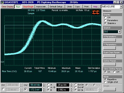
Timing Measurements Period, Frequency, Pos Width, Neg Width, Rise Time, Fall Time, Pos Duty Cycle, Neg Duty Cycle, Pos Crossing, Neg Crossing, Burst Width, Cycles, Time@Maximum, Time@Minimum. |
||||||||||||||||||||||||
|
Dual-Channel Measurements Delay, Gain. |
||||||||||||||||||||||||
|
FFT Measurements FFT Magnitude, FFT Delta Magnitude, THD, FFT Frequency, FFT Delta Frequency. |
||||||||||||||||||||||||
|
Measurement Statistics Display minimum, maximum, mean and standard deviation on any displayed waveform measurements. |
||||||||||||||||||||||||
|
Histicons A miniature histograms of parameter measurements that appear in Measurement Area. These thumbnail histograms let you see at a glance the statistical distribution of each parameter. |
||||||||||||||||||||||||
|
Method of Top-Base Definition Histogram, Min/Max, or User Defined (in absolute voltage). |
||||||||||||||||||||||||
|
Thresholds Settable in percentage, voltage or divisions. Standard thresholds are 10-50-90 % or 20-50-80 %. |
||||||||||||||||||||||||
|
MarginsAny region of the waveform may be isolated for measurement using vertical bars. Any region of the waveform may be isolated for measurement using vertical bars. |
||||||||||||||||||||||||
|
Measurement Mode Repetitive or Single-shot. |
||||||||||||||||||||||||
|
Limit Test Limit Test Signals can be tested by up to ten automatic parametric measurements and compared to user-defined test boundaries. Failure tolerances can be selected independently for each of the parametric tests. Limit test can be set to run continuously for a user-selected number of waveforms, or for a defined number of failures. |
||||||||||||||||||||||||
|
On failure actions Beep, Save failed waveform to disk or Stop acquisition. |
||||||||||||||||||||||||
|
Mathematics Waveform Math Up to four math waveforms can be defined and displayed using math functions F1-F4. |
||||||||||||||||||||||||
|
Math Operators Add, Subtract, Multiply, Divide, Invert, Absolute, Exponentiation (e), Exponentiation (10), Logarithm (e), Logarithm (10), Differentiate, Integrate, Inverse FFT, Linear Interpolation, Sin(x)/x Interpolation, Smoothing, Trend. |
||||||||||||||||||||||||
|
Operands Any channel, waveform memory, math function, spectrum, or constant can be selected as a source for one of two operands. |
||||||||||||||||||||||||
|
FFT FFT Up to two fast Fourier transforms can be run simultaneously. |
||||||||||||||||||||||||
|
Frequency Span Frequency Span = Sample Rate / 2 =Record Length / (2 x Time Base Range). |
||||||||||||||||||||||||
|
Frequency Resolution Frequency Resolution = Sample Rate / Record Length. |
||||||||||||||||||||||||
|
FFT Windows The built-in filters (Rectangular, Nicolson, Hanning, Flattop, Blackman- Harris and Kaiser-Bessel) allow optimization of frequency resolution, transients, and amplitude accuracy. |
||||||||||||||||||||||||
|
FFT Measurements Marker measurements can be made on frequency, delta frequency, magnitude, and delta magnitude. Automated FFT Measurements include: FFT Magnitude, FFT Delta Magnitude, THD, FFT Frequency, and FFT Delta Frequency. |
||||||||||||||||||||||||
|
Zoom Zoom feature The zoom feature allows waveforms (memories, functions, and spectrums) to be expanded and positioned in both vertical and horizontal axes. Allows precise comparison and study of fine waveform detail without affecting ongoing acquisitions. |
||||||||||||||||||||||||
|
Complex Scale You can select different Complex Scale: Magnitude, Phase, Magnitude + Phase, Real, Imaginary, and Real + Imaginary. |
||||||||||||||||||||||||
|
Vertical expanding and positioning Zoom provides a vertical dynamic range of 10 mln. divisions or 1 mln. screens. |
||||||||||||||||||||||||
|
Horizontal expanding and positioning Zoom provides a horizontal dynamic range of 640 divisions or 64 screens. |
||||||||||||||||||||||||
|
Histogram Histogram Axis Vertical, or Horizontal. Both vertical and horizontal histograms, with periodically updated measurements, allow statistical distributions to be analyzed over any region of the signal. |
||||||||||||||||||||||||
|
Histogram Measurement Set Scale, Offset, Hits in Box, Peak Hits, Pk-Pk, Median, Mean, Standard Deviation, Mean ± 1 Std Dev, Mean ± 2 Std Dev, Mean ± 3 Std Dev. |
||||||||||||||||||||||||
|
Histogram Window The histogram window determines which part of the database is used to plot the histogram. You can set the size of the histogram window to be any size that you want within the horizontal and vertical scaling limits of the scope. |
||||||||||||||||||||||||
|
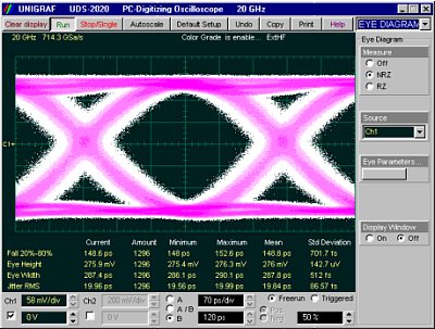
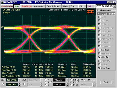
Eye-Diagram Eye Diagram The UDS-2000s has ability to automatically characterize NRZ and RZ eye pattern. Measurements are based upon statistical analysis of the waveform. |
||||||||||||||||||||||||
|
NRZ Measurement Set AC RMS, Area, Bit Rate, Bit Time, Crossing %, Crossing Level, Crossing Time, Cycle Area, Duty Cycle Distortion (%, s), Extinction Ratio (dB, %, ratio), Eye Amplitude, Eye High, Eye Width (%, s), Fall Time, Frequency, Jitter (P-p, RMS), Max, Mean, Mid, Min, Neg Overshoot, Noise P-p (One, Zero), Noise RMS, One Level, Peak-Peak, Pos. Overshoot, Period, Rise Time, RMS, Signal-to-Noise, Zero Level. |
||||||||||||||||||||||||
|
RZ Measurement Set AC RMS, Area, Bit Rate, Bit Time, Contrast Ratio (dB, %, ratio), Cycle Area, Eye Amplitude, Eye High, Eye Opening Factor, Eye Width (%, s), Fall Time, Jitter (P-p, RMS), Max, Mean, Mid, Min, RMS, Rise, Fall, Neg Crossing, Noise P-p (One, Zero), Noise RMS, One Level, Peak-Peak, Pos. Crossing, Pos. Duty Cycle, Pulse Width, Rise Time, RMS, Signal-to-Noise, Zero Level. |
||||||||||||||||||||||||
|
Mask Test Mask Test Acquired signals are tested for fit outside areas defined by up to eight polygons. Any samples that fall within the polygon boundaries result in test failures. Masks can be loaded from disk, or created automatically or manually. |
||||||||||||||||||||||||
|
Mask Creation You can create the following Mask: Standard predefined Mask, Automask, Mask saved on disk, Create new mask, Edit any mask. |
||||||||||||||||||||||||
|
Standard Mask Standard predefined optical or standard electrical masks can be created.SONET/SDH: OC1/STMO, OC3/STM1, OC9/STM3, OC12/STM4, OC18/STM6, OC48/STM16, FEC2666, OC192/STM64, FEC1066, FEC1071, FEC4266, FEC4302; Fiber Channel: FC133, FC266, FC531, FC1063, FC2125, FC4250, 10GFC; Ethernet: GB Ethernet, 2XGB Ethernet, 10GB Ethernet, 10GBE Ethernet, 10XGB Ethernet; INFIBAND, XAUI; ITU G.703: DS1, DS2, 8 Mb, DS3, 140 Mb; ANSI T1/102: DS1, DS1C, DS2, DS3, STS1 Eye, STS1 Pulse, STS3. |
||||||||||||||||||||||||
|
Mask Margin Available for industry standard mask testing. |
||||||||||||||||||||||||
|
Automask Creation Masks are created automatically for single-valued voltage signals. Automask specifies both delta X and delta Y tolerances. The failure actions are identical to those of limit testing. |
||||||||||||||||||||||||
|
Data collected during test Total number of waveforms examined, number of failed samples, number of hits within each polygon boundary. |
||||||||||||||||||||||||
|
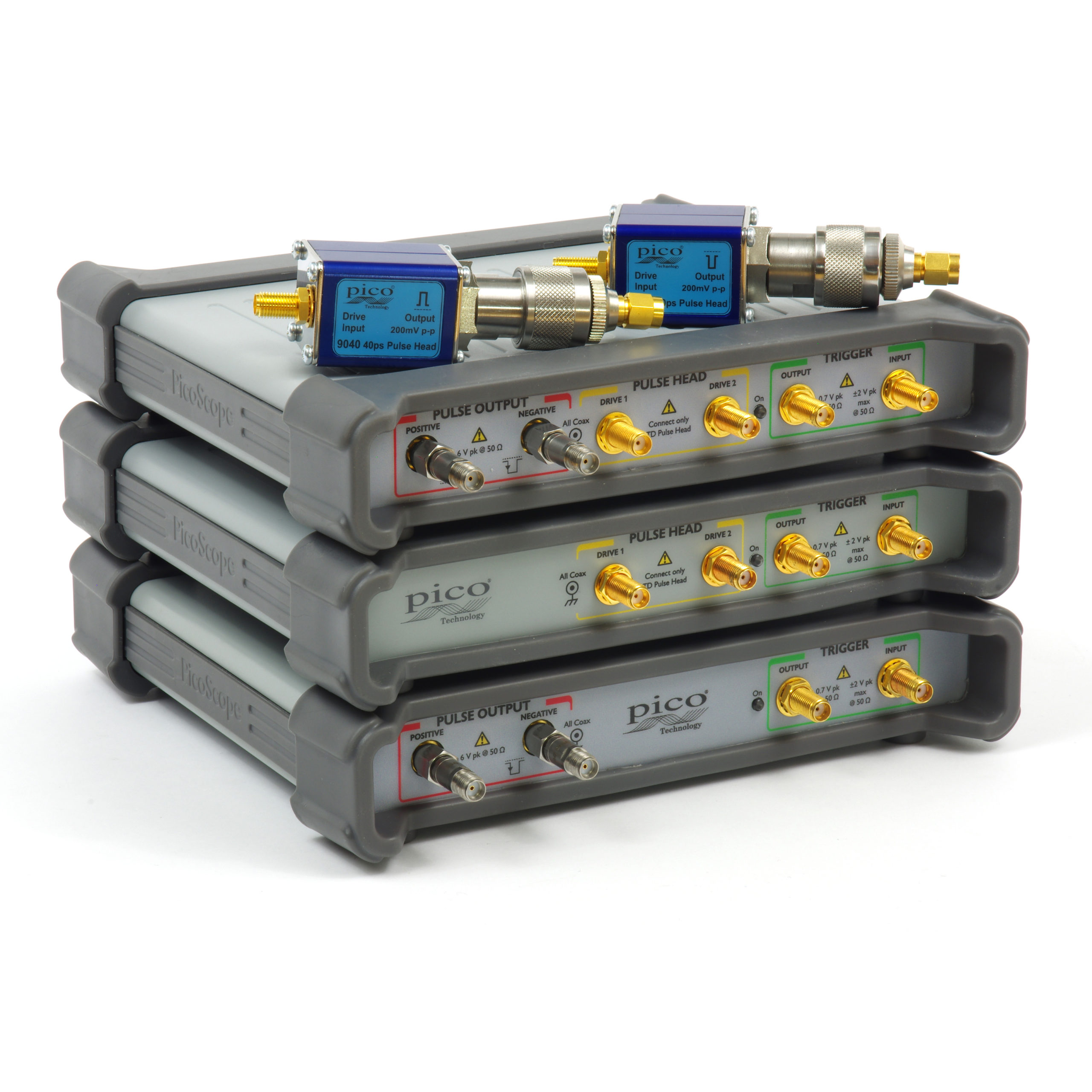
UDX-G01 Pulse Head The UDX-G01 Pulse Head is a fast tunnel-diode step generator designed for use with the UDS-2000 Series PC-Sampling Oscilloscopes for short-distance 40-ps TDR/TDT. See UDX-G01 for details. |
||||||||||||||||||||||||
|
Calibrators Vertical Calibrator Modes: DC, Pseudo-meander, or Off. Adjustable Output Range: -1.0 V to +1.0 V terminated into 50 OHm. Output Voltage Accuracy: ± 0.25 % of Output Voltage ± 1 mV. |
||||||||||||||||||||||||
|
Horizontal Calibrator Waveform: Square-Wave. Polarity: Positive from ground. Adjustable Period: 80 ns to 2 ms. Period Accuracy: ± 0.01 % of Period. Output Voltage: >700 mV terminated into 50 OHm. |
||||||||||||||||||||||||
|
DSO to PC Interface Type USB 2.0 (FS) or IEEE1284 (ECP mode) |
||||||||||||||||||||||||
|
Environmental Characteristics Temperature Operating: + 5°C to + 40°C. Non-operating: -40°C to + 50°C. |
||||||||||||||||||||||||
|
Humidity Operating: up to 85 % relative humidity (non-condensing) at + 25°C. |
||||||||||||||||||||||||
|
Power Requirements Voltage 95 to 125 VAC or 190 to 250 VAC. |
||||||||||||||||||||||||
|
Frequency 48 to 66 Hz single phase. |
||||||||||||||||||||||||
|
Power 60 VA maximum. |
||||||||||||||||||||||||
|
Physical Characteristics Dimensions Width (with handle): 270 mm, Width (without handle): 240 mm, Height: 102 mm, Depth (with handle): 420 mm, Depth (without handle): 377 mm. |
||||||||||||||||||||||||
|
Weight Net: 5.5 kg, Shipping: 12.0 kg. |
||||||||||||||||||||||||
Downloads
Manuals:
UDS-2000 PC-Sampling Oscilloscopes
DataSheets:
UDS-2030 * UDS-2020 * UDS-2012 Series PC–Sampling Oscilloscopes
UDS-2128 * UDS-2113 Series PC–Communication Analyzers
UDS-2022 * UDS-2021 Series PC-Sampling Oscilloscopes/TDR/TDT
Application Notes:
UDS-2128 PC-Communication Analyzer.
UDS-2020 PC-Sampling Oscilloscope – Measurments
UDS-2030 * UDS-2020 * UDS-2012 Series PC–Sampling Oscilloscopes